

404
R. Nagy et al.
due to time-varying disturbances (load, material stiffness, or damping) are applied
to an entire mechanical system and can be used to determine overall health of the
equipment.
The frequency of the steady-state vibration response resulting from the application
of a periodic, harmonic input should be equal to the frequency of the applied force
or motion, with the response magnitude being dependent on the actual mechanical
system.
Vibration analysis applied in an industrial or maintenance environment aims to
reduce maintenance costs and equipment downtime by detecting equipment faults
and can be used as predictive maintenance [2].
In this paper, we present the vibration response of custom made high-pressure
compressor under various pressure loads (10, 20, 30, 40 bar) with 1 or 2 charging
stages and the necessary time needed to attain the desired pressure.
2 Background
In the context of a multidimensional material testing of mechanical properties (force,
displacement, pressure, temperature), a high-pressure pneumatic source was required
to operate and supply compressed air in sufficient quantity and pressure to suit the
capacity of the tested elastic materials. The operational reliability and service life of
the pneumatic system depend to a large extent on the preparation of the compressed
air, but also on the vibrations that occur internally, due to loose connection and
elastic elements and cooling [3, 4]. Switching the compressors on and off, pressure
fluctuations occur which have an unfavorable effect on the functioning of the system.
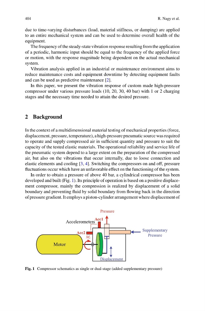
In order to obtain a pressure of above 40 bar, a cylindrical compressor has been
developed and built (Fig. 1). Its principle of operation is based on a positive displacement compressor, mainly the compression is realized by displacement of a solid
boundary and preventing fluid by solid boundary from flowing back in the direction
of pressure gradient. It employs a piston-cylinder arrangement where displacement of
Motor
Pressure
Displacement
M t
Supplementary
Pressure
Accelerometers
Acc1
Acc2
Fig. 1 Compressor schematics as single or dual-stage (added supplementary pressure)
R. Nagy et al.
due to time-varying disturbances (load, material stiffness, or damping) are applied
to an entire mechanical system and can be used to determine overall health of the
equipment.
The frequency of the steady-state vibration response resulting from the application
of a periodic, harmonic input should be equal to the frequency of the applied force
or motion, with the response magnitude being dependent on the actual mechanical
system.
Vibration analysis applied in an industrial or maintenance environment aims to
reduce maintenance costs and equipment downtime by detecting equipment faults
and can be used as predictive maintenance [2].
In this paper, we present the vibration response of custom made high-pressure
compressor under various pressure loads (10, 20, 30, 40 bar) with 1 or 2 charging
stages and the necessary time needed to attain the desired pressure.
2 Background
In the context of a multidimensional material testing of mechanical properties (force,
displacement, pressure, temperature), a high-pressure pneumatic source was required
to operate and supply compressed air in sufficient quantity and pressure to suit the
capacity of the tested elastic materials. The operational reliability and service life of
the pneumatic system depend to a large extent on the preparation of the compressed
air, but also on the vibrations that occur internally, due to loose connection and
elastic elements and cooling [3, 4]. Switching the compressors on and off, pressure
fluctuations occur which have an unfavorable effect on the functioning of the system.
In order to obtain a pressure of above 40 bar, a cylindrical compressor has been
developed and built (Fig. 1). Its principle of operation is based on a positive displacement compressor, mainly the compression is realized by displacement of a solid
boundary and preventing fluid by solid boundary from flowing back in the direction
of pressure gradient. It employs a piston-cylinder arrangement where displacement of
Motor
Pressure
Displacement
M t
Supplementary
Pressure
Accelerometers
Acc1
Acc2
Fig. 1 Compressor schematics as single or dual-stage (added supplementary pressure)