

Experimental Analysis of Noise and Chatter Detection in Milling …
339
Table 6 The results of experiment 1.3
Third experiment
No.
1
2
3
4
5
6
7
8
Spindle speed [rpm] 600
700
800
900
1000
1100
1200
1300
L Fmax
[dBA]
84.8
89.8
85.0
85.4
85.1
86.9
85.8
86.5
L eq
[dBA]
82.2
84.6
83.2
84.0
83.1
84.7
83.9
84.7
Table 7 The results of experiment 1.4
Fourth experiment
No.
1
2
3
4
5
6
7
8
Radial depth [mm]
5
10
15
20
25
30
35
40
L Fmax [dBA]
84.2
86.1
88.2
89.1
91.9
97.4
97.7
95.4
L eq
[dBA]
82.3
84.6
84.8
85.4
89.6
94.9
96.2
93.7
3.2 The Second Experiment
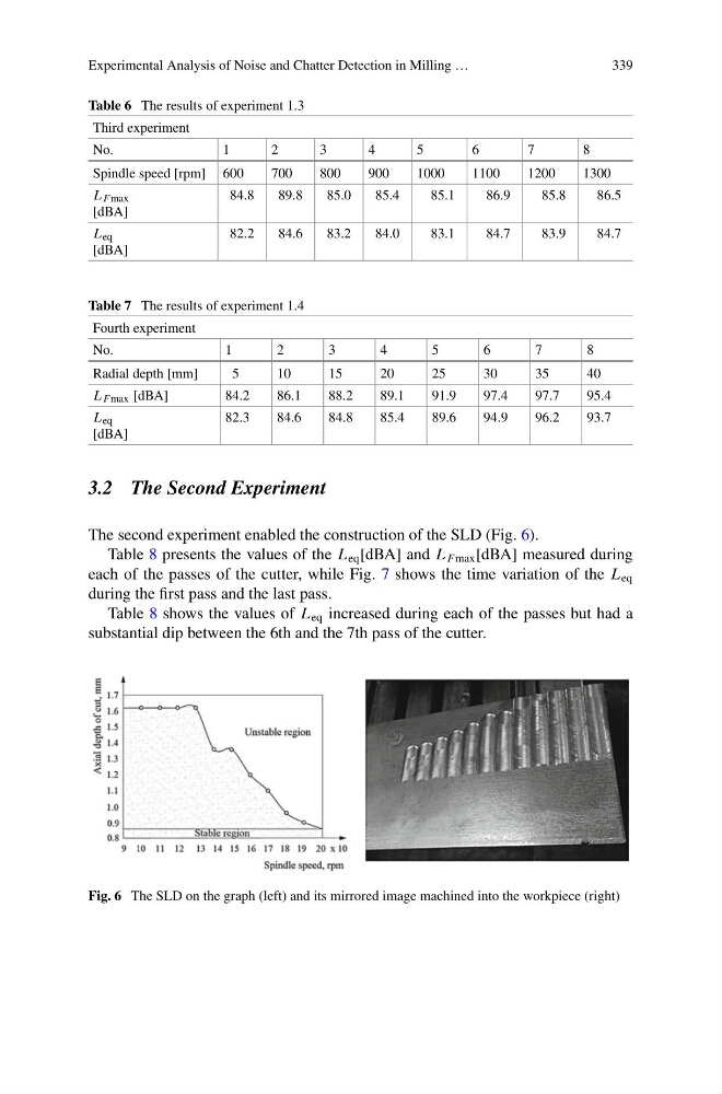
The second experiment enabled the construction of the SLD (Fig. 6).
Table 8 presents the values of the L eq [dBA] and L Fmax [dBA] measured during
each of the passes of the cutter, while Fig. 7 shows the time variation of the L eq
during the first pass and the last pass.
Table 8 shows the values of L eq increased during each of the passes but had a
substantial dip between the 6th and the 7th pass of the cutter.
Fig. 6 The SLD on the graph (left) and its mirrored image machined into the workpiece (right)
339
Table 6 The results of experiment 1.3
Third experiment
No.
1
2
3
4
5
6
7
8
Spindle speed [rpm] 600
700
800
900
1000
1100
1200
1300
L Fmax
[dBA]
84.8
89.8
85.0
85.4
85.1
86.9
85.8
86.5
L eq
[dBA]
82.2
84.6
83.2
84.0
83.1
84.7
83.9
84.7
Table 7 The results of experiment 1.4
Fourth experiment
No.
1
2
3
4
5
6
7
8
Radial depth [mm]
5
10
15
20
25
30
35
40
L Fmax [dBA]
84.2
86.1
88.2
89.1
91.9
97.4
97.7
95.4
L eq
[dBA]
82.3
84.6
84.8
85.4
89.6
94.9
96.2
93.7
3.2 The Second Experiment
The second experiment enabled the construction of the SLD (Fig. 6).
Table 8 presents the values of the L eq [dBA] and L Fmax [dBA] measured during
each of the passes of the cutter, while Fig. 7 shows the time variation of the L eq
during the first pass and the last pass.
Table 8 shows the values of L eq increased during each of the passes but had a
substantial dip between the 6th and the 7th pass of the cutter.
Fig. 6 The SLD on the graph (left) and its mirrored image machined into the workpiece (right)