

Solution of the Environmental Noise Problem Generated …
151
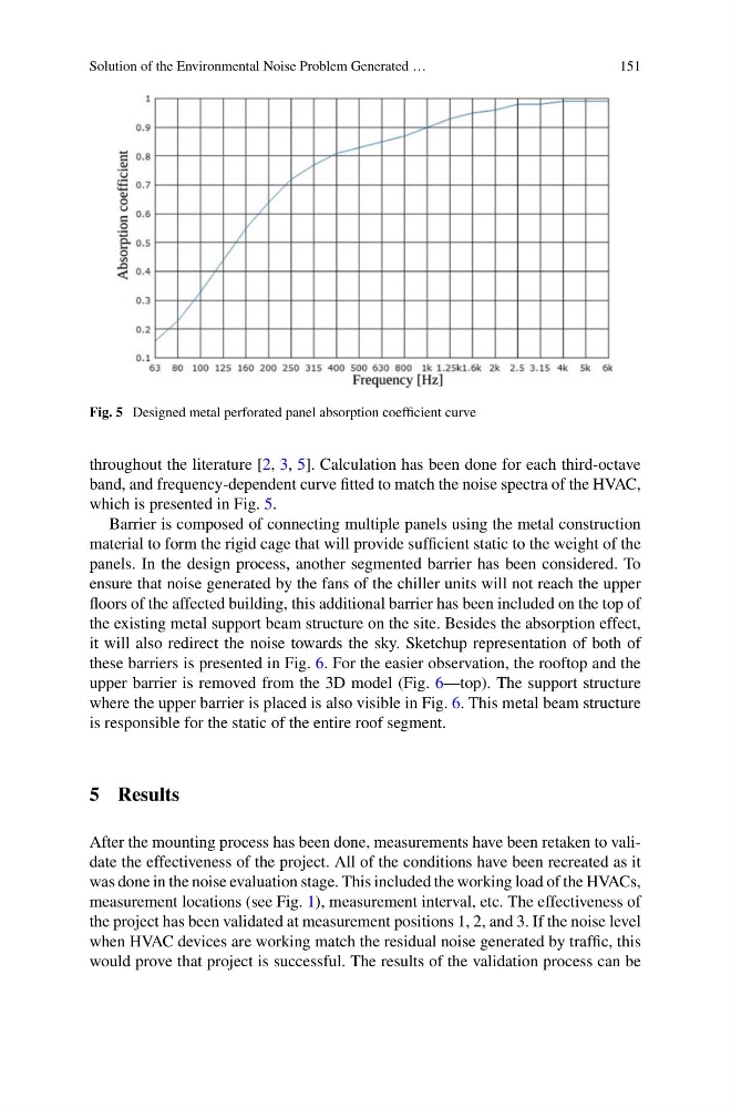
Fig. 5 Designed metal perforated panel absorption coefficient curve
throughout the literature [2, 3, 5]. Calculation has been done for each third-octave
band, and frequency-dependent curve fitted to match the noise spectra of the HVAC,
which is presented in Fig. 5.
Barrier is composed of connecting multiple panels using the metal construction
material to form the rigid cage that will provide sufficient static to the weight of the
panels. In the design process, another segmented barrier has been considered. To
ensure that noise generated by the fans of the chiller units will not reach the upper
floors of the affected building, this additional barrier has been included on the top of
the existing metal support beam structure on the site. Besides the absorption effect,
it will also redirect the noise towards the sky. Sketchup representation of both of
these barriers is presented in Fig. 6. For the easier observation, the rooftop and the
upper barrier is removed from the 3D model (Fig. 6—top). The support structure
where the upper barrier is placed is also visible in Fig. 6. This metal beam structure
is responsible for the static of the entire roof segment.
5 Results
After the mounting process has been done, measurements have been retaken to validate the effectiveness of the project. All of the conditions have been recreated as it
was done in the noise evaluation stage. This included the working load of the HVACs,
measurement locations (see Fig. 1), measurement interval, etc. The effectiveness of
the project has been validated at measurement positions 1, 2, and 3. If the noise level
when HVAC devices are working match the residual noise generated by traffic, this
would prove that project is successful. The results of the validation process can be
151
Fig. 5 Designed metal perforated panel absorption coefficient curve
throughout the literature [2, 3, 5]. Calculation has been done for each third-octave
band, and frequency-dependent curve fitted to match the noise spectra of the HVAC,
which is presented in Fig. 5.
Barrier is composed of connecting multiple panels using the metal construction
material to form the rigid cage that will provide sufficient static to the weight of the
panels. In the design process, another segmented barrier has been considered. To
ensure that noise generated by the fans of the chiller units will not reach the upper
floors of the affected building, this additional barrier has been included on the top of
the existing metal support beam structure on the site. Besides the absorption effect,
it will also redirect the noise towards the sky. Sketchup representation of both of
these barriers is presented in Fig. 6. For the easier observation, the rooftop and the
upper barrier is removed from the 3D model (Fig. 6—top). The support structure
where the upper barrier is placed is also visible in Fig. 6. This metal beam structure
is responsible for the static of the entire roof segment.
5 Results
After the mounting process has been done, measurements have been retaken to validate the effectiveness of the project. All of the conditions have been recreated as it
was done in the noise evaluation stage. This included the working load of the HVACs,
measurement locations (see Fig. 1), measurement interval, etc. The effectiveness of
the project has been validated at measurement positions 1, 2, and 3. If the noise level
when HVAC devices are working match the residual noise generated by traffic, this
would prove that project is successful. The results of the validation process can be