

82 The Bennett linkage
lengths proportional to a and b, and twists being α and β, which are
denoted as ‘I’ in Figure 5.3(a). The second type, next to the first one, are
made of Bennett linkages with lengths proportional to a and b, and twists
being α i and β i or –α i and –β i , which are denoted as ‘II i ’ or ‘–II i ’ (i = 1, 3,
5, . . .), respectively, and both α i and β i satisfy Eq. (5.15).
A further analysis has shown that the rows of Bennett linkages in Figure
5.3(a) marked ‘I’ can actually have different twists from other rows where
only one type of Bennett linkages is allowed. A more general solution is
given in Figure 5.3(b) in which the Bennett linkages ‘I’ are replaced by ‘I k ’
(k = 2, 4, 6, . . .). A very interesting pattern now emerges: diagonally from
top left to bottom right, each row of the Bennett linkages belong to the
same type. This leads to the following important feature. If a set of straight
and parallel guidelines are drawn diagonally from top left to bottom right,
each of which passes through a number of revolute joints, these lines
remain straight and parallel to each other during deployment though the
distances between the guidelines may vary.
5.2.2 Expanded shapes
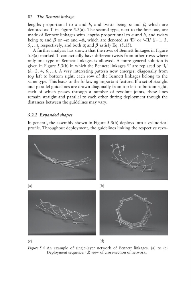
In general, the assembly shown in Figure 5.3(b) deploys into a cylindrical
profile. Throughout deployment, the guidelines linking the respective revo(a)
(b)
(c)
(d)
Figure 5.4 An example of single-layer network of Bennett linkages. (a) to (c)
Deployment sequence; (d) view of cross-section of network.
lengths proportional to a and b, and twists being α and β, which are
denoted as ‘I’ in Figure 5.3(a). The second type, next to the first one, are
made of Bennett linkages with lengths proportional to a and b, and twists
being α i and β i or –α i and –β i , which are denoted as ‘II i ’ or ‘–II i ’ (i = 1, 3,
5, . . .), respectively, and both α i and β i satisfy Eq. (5.15).
A further analysis has shown that the rows of Bennett linkages in Figure
5.3(a) marked ‘I’ can actually have different twists from other rows where
only one type of Bennett linkages is allowed. A more general solution is
given in Figure 5.3(b) in which the Bennett linkages ‘I’ are replaced by ‘I k ’
(k = 2, 4, 6, . . .). A very interesting pattern now emerges: diagonally from
top left to bottom right, each row of the Bennett linkages belong to the
same type. This leads to the following important feature. If a set of straight
and parallel guidelines are drawn diagonally from top left to bottom right,
each of which passes through a number of revolute joints, these lines
remain straight and parallel to each other during deployment though the
distances between the guidelines may vary.
5.2.2 Expanded shapes
In general, the assembly shown in Figure 5.3(b) deploys into a cylindrical
profile. Throughout deployment, the guidelines linking the respective revo(a)
(b)
(c)
(d)
Figure 5.4 An example of single-layer network of Bennett linkages. (a) to (c)
Deployment sequence; (d) view of cross-section of network.