

78 The Bennett linkage
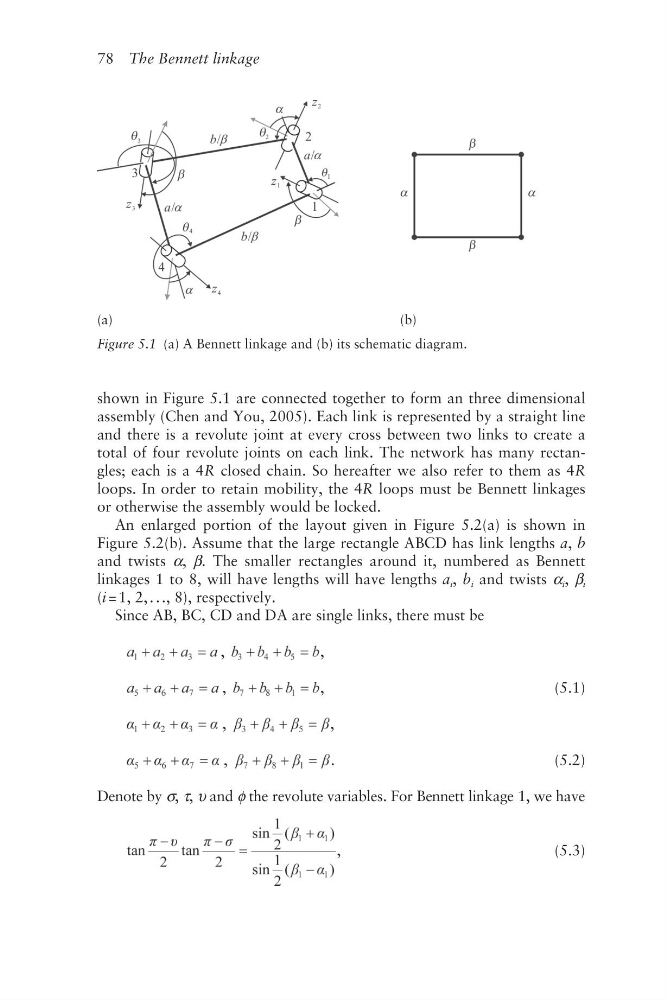
shown in Figure 5.1 are connected together to form an three dimensional
assembly (Chen and You, 2005). Each link is represented by a straight line
and there is a revolute joint at every cross between two links to create a
total of four revolute joints on each link. The network has many rectangles; each is a 4R closed chain. So hereafter we also refer to them as 4R
loops. In order to retain mobility, the 4R loops must be Bennett linkages
or otherwise the assembly would be locked.
An enlarged portion of the layout given in Figure 5.2(a) is shown in
Figure 5.2(b). Assume that the large rectangle ABCD has link lengths a, b
and twists α, β. The smaller rectangles around it, numbered as Bennett
linkages 1 to 8, will have lengths will have lengths a i , b i and twists α i , β i
(i = 1, 2, . . ., 8), respectively.
Since AB, BC, CD and DA are single links, there must be
,
,
,
,
(5.1)
,
,
,
.
(5.2)
Denote by σ, τ, υ and φ the revolute variables. For Bennett linkage 1, we have
,
(5.3)
(a)
(b)
Figure 5.1 (a) A Bennett linkage and (b) its schematic diagram.
shown in Figure 5.1 are connected together to form an three dimensional
assembly (Chen and You, 2005). Each link is represented by a straight line
and there is a revolute joint at every cross between two links to create a
total of four revolute joints on each link. The network has many rectangles; each is a 4R closed chain. So hereafter we also refer to them as 4R
loops. In order to retain mobility, the 4R loops must be Bennett linkages
or otherwise the assembly would be locked.
An enlarged portion of the layout given in Figure 5.2(a) is shown in
Figure 5.2(b). Assume that the large rectangle ABCD has link lengths a, b
and twists α, β. The smaller rectangles around it, numbered as Bennett
linkages 1 to 8, will have lengths will have lengths a i , b i and twists α i , β i
(i = 1, 2, . . ., 8), respectively.
Since AB, BC, CD and DA are single links, there must be
,
,
,
,
(5.1)
,
,
,
.
(5.2)
Denote by σ, τ, υ and φ the revolute variables. For Bennett linkage 1, we have
,
(5.3)
(a)
(b)
Figure 5.1 (a) A Bennett linkage and (b) its schematic diagram.