

64 Spatial rings and domes
2, . . ., 6 in Figure 4.2(a). All of the connections are revolute joints and the
chain folds to a compact bundle.
The chain has a total of sixteen links (n = 16), including eight joint
pieces, and twenty revolute joints (j = 20), each of which has one degree of
freedom (f i = 1). The mobility criterion given by Eq. (2.1) therefore yields a
value of –10. However, as all of the scissor- like elements can have the same
pivoting angles because of symmetry it is an overconstrained mechanism.
Its top projection on the ground is always a rectangle as shown by the
schematic diagram in Figure 4.2(b) in which the thick solid lines are projections of elements and little dashes represent revolute joints. Moreover, if
the dimension of the joints is considerably smaller than that of the elements, the schematic diagram becomes that in Figure 4.2(c). Note that,
though the joint dimensions may be neglected as far as the overall assembly is concerned, they have to be taken into account at a later stage in
order to ensure the assembly is a true mechanism.
The above method for construction of the spatial mobile chain can be
extended to include more or fewer conventional scissor- like elements. For
instance, a closed chain with three scissor- like elements of the same type
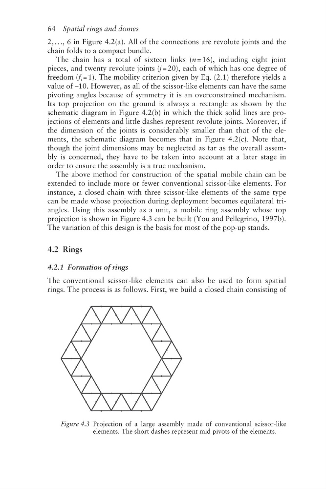
can be made whose projection during deployment becomes equilateral triangles. Using this assembly as a unit, a mobile ring assembly whose top
projection is shown in Figure 4.3 can be built (You and Pellegrino, 1997b).
The variation of this design is the basis for most of the pop- up stands.
4.2 Rings
4.2.1 Formation of rings
The conventional scissor- like elements can also be used to form spatial
rings. The process is as follows. First, we build a closed chain consisting of
Figure 4.3 Projection of a large assembly made of conventional scissor-like
elements. The short dashes represent mid pivots of the elements.
2, . . ., 6 in Figure 4.2(a). All of the connections are revolute joints and the
chain folds to a compact bundle.
The chain has a total of sixteen links (n = 16), including eight joint
pieces, and twenty revolute joints (j = 20), each of which has one degree of
freedom (f i = 1). The mobility criterion given by Eq. (2.1) therefore yields a
value of –10. However, as all of the scissor- like elements can have the same
pivoting angles because of symmetry it is an overconstrained mechanism.
Its top projection on the ground is always a rectangle as shown by the
schematic diagram in Figure 4.2(b) in which the thick solid lines are projections of elements and little dashes represent revolute joints. Moreover, if
the dimension of the joints is considerably smaller than that of the elements, the schematic diagram becomes that in Figure 4.2(c). Note that,
though the joint dimensions may be neglected as far as the overall assembly is concerned, they have to be taken into account at a later stage in
order to ensure the assembly is a true mechanism.
The above method for construction of the spatial mobile chain can be
extended to include more or fewer conventional scissor- like elements. For
instance, a closed chain with three scissor- like elements of the same type
can be made whose projection during deployment becomes equilateral triangles. Using this assembly as a unit, a mobile ring assembly whose top
projection is shown in Figure 4.3 can be built (You and Pellegrino, 1997b).
The variation of this design is the basis for most of the pop- up stands.
4.2 Rings
4.2.1 Formation of rings
The conventional scissor- like elements can also be used to form spatial
rings. The process is as follows. First, we build a closed chain consisting of
Figure 4.3 Projection of a large assembly made of conventional scissor-like
elements. The short dashes represent mid pivots of the elements.