

12 Fundamental concepts
The closure equation is particularly useful in determining algebraically
the relationship between the inputs and outputs. Take the four- bar linkage
shown in Figure 2.6(b) as an example. Link 4 is chosen as ground and the
links are represented by vectors p i (i = 1, 2, 3 and 4). The closure equation
(2.5) is
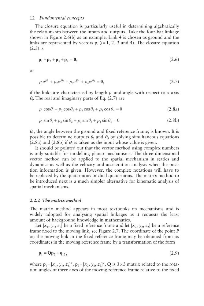
,
(2.6)
or
,
(2.7)
if the links are characterised by length p i and angle with respect to x axis
θ i . The real and imaginary parts of Eq. (2.7) are
(2.8a)
(2.8b)
θ 4 , the angle between the ground and fixed reference frame, is known. It is
possible to determine outputs θ 2 and θ 3 by solving simultaneous equations
(2.8a) and (2.8b) if θ 1 is taken as the input whose value is given.
It should be pointed out that the vector method using complex numbers
is only suitable for modelling planar mechanisms. The three dimensional
vector method can be applied to the spatial mechanism in statics and
dynamics as well as the velocity and acceleration analysis when the position information is given. However, the complex notations will have to
be replaced by the quaternions or dual quaternions. The matrix method to
be introduced next is a much simpler alternative for kinematic analysis of
spatial mechanisms.
2.2.2 The matrix method
The matrix method appears in most textbooks on mechanisms and is
widely adopted for analysing spatial linkages as it requests the least
amount of background knowledge in mathematics.
Let [x 1 , y 1 , z 1 ] be a fixed reference frame and let [x 2 , y 2 , z 2 ] be a reference
frame fixed to the moving link, see Figure 2.7. The coordinate of the point P
on the moving link in the fixed reference frame may be obtained from its
coordinates in the moving reference frame by a transformation of the form
,
(2.9)
where p 1 = [x 1 , y 1 , z 1 ]
T
, p 2 = [x 2 , y 2 , z 2 ]
T
, Q is 3 × 3 matrix related to the rotation angles of three axes of the moving reference frame relative to the fixed
The closure equation is particularly useful in determining algebraically
the relationship between the inputs and outputs. Take the four- bar linkage
shown in Figure 2.6(b) as an example. Link 4 is chosen as ground and the
links are represented by vectors p i (i = 1, 2, 3 and 4). The closure equation
(2.5) is
,
(2.6)
or
,
(2.7)
if the links are characterised by length p i and angle with respect to x axis
θ i . The real and imaginary parts of Eq. (2.7) are
(2.8a)
(2.8b)
θ 4 , the angle between the ground and fixed reference frame, is known. It is
possible to determine outputs θ 2 and θ 3 by solving simultaneous equations
(2.8a) and (2.8b) if θ 1 is taken as the input whose value is given.
It should be pointed out that the vector method using complex numbers
is only suitable for modelling planar mechanisms. The three dimensional
vector method can be applied to the spatial mechanism in statics and
dynamics as well as the velocity and acceleration analysis when the position information is given. However, the complex notations will have to
be replaced by the quaternions or dual quaternions. The matrix method to
be introduced next is a much simpler alternative for kinematic analysis of
spatial mechanisms.
2.2.2 The matrix method
The matrix method appears in most textbooks on mechanisms and is
widely adopted for analysing spatial linkages as it requests the least
amount of background knowledge in mathematics.
Let [x 1 , y 1 , z 1 ] be a fixed reference frame and let [x 2 , y 2 , z 2 ] be a reference
frame fixed to the moving link, see Figure 2.7. The coordinate of the point P
on the moving link in the fixed reference frame may be obtained from its
coordinates in the moving reference frame by a transformation of the form
,
(2.9)
where p 1 = [x 1 , y 1 , z 1 ]
T
, p 2 = [x 2 , y 2 , z 2 ]
T
, Q is 3 × 3 matrix related to the rotation angles of three axes of the moving reference frame relative to the fixed