

The Bricard linkages 119
This means that all of the threefold- symmetric Bricard linkages can be
flattened to form a planar equilateral triangle whose side length is 2l.
Additionally, when 0 ≤ α ≤ π/3 or 2π/3 < α ≤ π, the movement of the linkages is not continuous. It has been found by experiment that the linkage
is physically blocked in the positions when all the links are crossed in the
centre when either θ 1 or θ 2 reaches π or –π. Figure 6.3 shows two configurations of a model with α = π/4. The input–output curve forms a closed
loop when π/3 ≤ α ≤ 2π/3 and thus the linkage keeps moving continuously.
A model with α = 5π/12 is shown in Figure 6.4, with a continuous range
of movement.
Now focus on a particular set of input–output curves in Figure 6.2 when
α = π/3 or 2π/3. Both θ 1 and θ 2 reach π or –π simultaneously, which correspond to the configurations of the most compact folding where all of the
links fold to a bundle. On the other hand, when θ 1 = 0, θ 2 = 2π/3 (or –2π/3),
or vice versa, the linkage forms a plane equilateral triangle, in accordance
to the configuration of maximum expansion. The motion sequence of a
model with α = π/3 is shown in Figure 6.5, which confirms the above findings. Because this particular threefold- symmetric Bricard linkage with twist
of π/3 or 2π/3 can achieve both compact folding and maximum expansion,
it is an ideal building block for construction of large mobile assemblies,
which will be discussed next.
The threefold- symmetric Bricard linkages with twist π/3 or 2π/3 have
the same behaviour and therefore only α = π/3 is considered hereafter. This
particular linkage can be represented by the schematic diagram shown
in Figure 6.6(a), in which the hinge connecting the ends of the links is
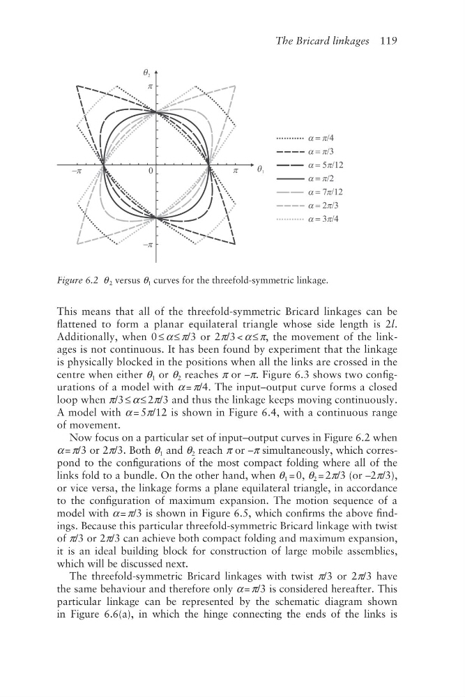
Figure 6.2 θ 2 versus θ 1 curves for the threefold-symmetric linkage.
This means that all of the threefold- symmetric Bricard linkages can be
flattened to form a planar equilateral triangle whose side length is 2l.
Additionally, when 0 ≤ α ≤ π/3 or 2π/3 < α ≤ π, the movement of the linkages is not continuous. It has been found by experiment that the linkage
is physically blocked in the positions when all the links are crossed in the
centre when either θ 1 or θ 2 reaches π or –π. Figure 6.3 shows two configurations of a model with α = π/4. The input–output curve forms a closed
loop when π/3 ≤ α ≤ 2π/3 and thus the linkage keeps moving continuously.
A model with α = 5π/12 is shown in Figure 6.4, with a continuous range
of movement.
Now focus on a particular set of input–output curves in Figure 6.2 when
α = π/3 or 2π/3. Both θ 1 and θ 2 reach π or –π simultaneously, which correspond to the configurations of the most compact folding where all of the
links fold to a bundle. On the other hand, when θ 1 = 0, θ 2 = 2π/3 (or –2π/3),
or vice versa, the linkage forms a plane equilateral triangle, in accordance
to the configuration of maximum expansion. The motion sequence of a
model with α = π/3 is shown in Figure 6.5, which confirms the above findings. Because this particular threefold- symmetric Bricard linkage with twist
of π/3 or 2π/3 can achieve both compact folding and maximum expansion,
it is an ideal building block for construction of large mobile assemblies,
which will be discussed next.
The threefold- symmetric Bricard linkages with twist π/3 or 2π/3 have
the same behaviour and therefore only α = π/3 is considered hereafter. This
particular linkage can be represented by the schematic diagram shown
in Figure 6.6(a), in which the hinge connecting the ends of the links is
Figure 6.2 θ 2 versus θ 1 curves for the threefold-symmetric linkage.