

112 The Bennett linkage
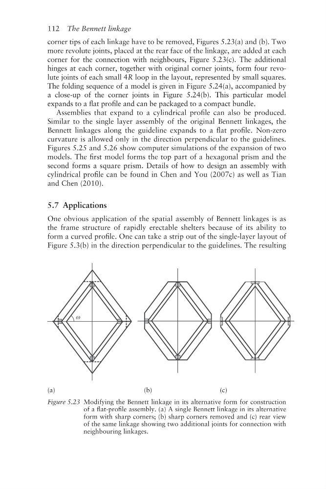
corner tips of each linkage have to be removed, Figures 5.23(a) and (b). Two
more revolute joints, placed at the rear face of the linkage, are added at each
corner for the connection with neighbours, Figure 5.23(c). The additional
hinges at each corner, together with original corner joints, form four revolute joints of each small 4R loop in the layout, represented by small squares.
The folding sequence of a model is given in Figure 5.24(a), accompanied by
a close- up of the corner joints in Figure 5.24(b). This particular model
expands to a flat profile and can be packaged to a compact bundle.
Assemblies that expand to a cylindrical profile can also be produced.
Similar to the single layer assembly of the original Bennett linkages, the
Bennett linkages along the guideline expands to a flat profile. Non- zero
curvature is allowed only in the direction perpendicular to the guidelines.
Figures 5.25 and 5.26 show computer simulations of the expansion of two
models. The first model forms the top part of a hexagonal prism and the
second forms a square prism. Details of how to design an assembly with
cylindrical profile can be found in Chen and You (2007c) as well as Tian
and Chen (2010).
5.7 Applications
One obvious application of the spatial assembly of Bennett linkages is as
the frame structure of rapidly erectable shelters because of its ability to
form a curved profile. One can take a strip out of the single- layer layout of
Figure 5.3(b) in the direction perpendicular to the guidelines. The resulting
(a)
(b)
(c)
Figure 5.23 Modifying the Bennett linkage in its alternative form for construction
of a flat-profile assembly. (a) A single Bennett linkage in its alternative
form with sharp corners; (b) sharp corners removed and (c) rear view
of the same linkage showing two additional joints for connection with
neighbouring linkages.
corner tips of each linkage have to be removed, Figures 5.23(a) and (b). Two
more revolute joints, placed at the rear face of the linkage, are added at each
corner for the connection with neighbours, Figure 5.23(c). The additional
hinges at each corner, together with original corner joints, form four revolute joints of each small 4R loop in the layout, represented by small squares.
The folding sequence of a model is given in Figure 5.24(a), accompanied by
a close- up of the corner joints in Figure 5.24(b). This particular model
expands to a flat profile and can be packaged to a compact bundle.
Assemblies that expand to a cylindrical profile can also be produced.
Similar to the single layer assembly of the original Bennett linkages, the
Bennett linkages along the guideline expands to a flat profile. Non- zero
curvature is allowed only in the direction perpendicular to the guidelines.
Figures 5.25 and 5.26 show computer simulations of the expansion of two
models. The first model forms the top part of a hexagonal prism and the
second forms a square prism. Details of how to design an assembly with
cylindrical profile can be found in Chen and You (2007c) as well as Tian
and Chen (2010).
5.7 Applications
One obvious application of the spatial assembly of Bennett linkages is as
the frame structure of rapidly erectable shelters because of its ability to
form a curved profile. One can take a strip out of the single- layer layout of
Figure 5.3(b) in the direction perpendicular to the guidelines. The resulting
(a)
(b)
(c)
Figure 5.23 Modifying the Bennett linkage in its alternative form for construction
of a flat-profile assembly. (a) A single Bennett linkage in its alternative
form with sharp corners; (b) sharp corners removed and (c) rear view
of the same linkage showing two additional joints for connection with
neighbouring linkages.