

The Bennett linkage 111
The design work can be done based on the values of L, λ and ω, though
it is much more convenient to use l, α and c (or d) when analysing the
kinematic behaviour of the linkage such as θ 1f , θ 2f , θ 1e and θ 2e . Several
models have been made which are shown in Figures 5.20 and 5.21 (Chen
and You, 2007a).
5.6 Assemblies of alternative form linkages
The Bennett linkage in its alternative forms can also be used to construct
large mobile assemblies with the same layout as that for the linkage in its
original form.
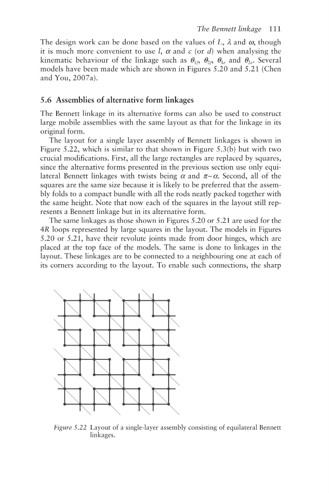
The layout for a single layer assembly of Bennett linkages is shown in
Figure 5.22, which is similar to that shown in Figure 5.3(b) but with two
crucial modifications. First, all the large rectangles are replaced by squares,
since the alternative forms presented in the previous section use only equilateral Bennett linkages with twists being α and π – α. Second, all of the
squares are the same size because it is likely to be preferred that the assembly folds to a compact bundle with all the rods neatly packed together with
the same height. Note that now each of the squares in the layout still represents a Bennett linkage but in its alternative form.
The same linkages as those shown in Figures 5.20 or 5.21 are used for the
4R loops represented by large squares in the layout. The models in Figures
5.20 or 5.21, have their revolute joints made from door hinges, which are
placed at the top face of the models. The same is done to linkages in the
layout. These linkages are to be connected to a neighbouring one at each of
its corners according to the layout. To enable such connections, the sharp
Figure 5.22 Layout of a single-layer assembly consisting of equilateral Bennett
linkages.
The design work can be done based on the values of L, λ and ω, though
it is much more convenient to use l, α and c (or d) when analysing the
kinematic behaviour of the linkage such as θ 1f , θ 2f , θ 1e and θ 2e . Several
models have been made which are shown in Figures 5.20 and 5.21 (Chen
and You, 2007a).
5.6 Assemblies of alternative form linkages
The Bennett linkage in its alternative forms can also be used to construct
large mobile assemblies with the same layout as that for the linkage in its
original form.
The layout for a single layer assembly of Bennett linkages is shown in
Figure 5.22, which is similar to that shown in Figure 5.3(b) but with two
crucial modifications. First, all the large rectangles are replaced by squares,
since the alternative forms presented in the previous section use only equilateral Bennett linkages with twists being α and π – α. Second, all of the
squares are the same size because it is likely to be preferred that the assembly folds to a compact bundle with all the rods neatly packed together with
the same height. Note that now each of the squares in the layout still represents a Bennett linkage but in its alternative form.
The same linkages as those shown in Figures 5.20 or 5.21 are used for the
4R loops represented by large squares in the layout. The models in Figures
5.20 or 5.21, have their revolute joints made from door hinges, which are
placed at the top face of the models. The same is done to linkages in the
layout. These linkages are to be connected to a neighbouring one at each of
its corners according to the layout. To enable such connections, the sharp
Figure 5.22 Layout of a single-layer assembly consisting of equilateral Bennett
linkages.