

2.2 Experimental Implementation and Analysis Methodology
37
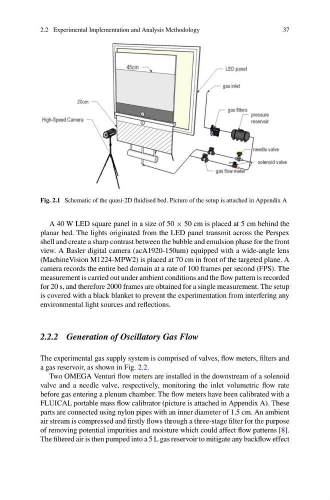
Fig. 2.1 Schematic of the quasi-2D fluidised bed. Picture of the setup is attached in Appendix A
A 40 W LED square panel in a size of 50 × 50 cm is placed at 5 cm behind the
planar bed. The lights originated from the LED panel transmit across the Perspex
shell and create a sharp contrast between the bubble and emulsion phase for the front
view. A Basler digital camera (acA1920-150um) equipped with a wide-angle lens
(MachineVision M1224-MPW2) is placed at 70 cm in front of the targeted plane. A
camera records the entire bed domain at a rate of 100 frames per second (FPS). The
measurement is carried out under ambient conditions and the flow pattern is recorded
for 20 s, and therefore 2000 frames are obtained for a single measurement. The setup
is covered with a black blanket to prevent the experimentation from interfering any
environmental light sources and reflections.
2.2.2 Generation of Oscillatory Gas Flow
The experimental gas supply system is comprised of valves, flow meters, filters and
a gas reservoir, as shown in Fig. 2.2.
Two OMEGA Venturi flow meters are installed in the downstream of a solenoid
valve and a needle valve, respectively, monitoring the inlet volumetric flow rate
before gas entering a plenum chamber. The flow meters have been calibrated with a
FLUICAL portable mass flow calibrator (picture is attached in Appendix A). These
parts are connected using nylon pipes with an inner diameter of 1.5 cm. An ambient
air stream is compressed and firstly flows through a three-stage filter for the purpose
of removing potential impurities and moisture which could affect flow patterns [8].
The filtered air is then pumped into a 5 L gas reservoir to mitigate any backflow effect
37
Fig. 2.1 Schematic of the quasi-2D fluidised bed. Picture of the setup is attached in Appendix A
A 40 W LED square panel in a size of 50 × 50 cm is placed at 5 cm behind the
planar bed. The lights originated from the LED panel transmit across the Perspex
shell and create a sharp contrast between the bubble and emulsion phase for the front
view. A Basler digital camera (acA1920-150um) equipped with a wide-angle lens
(MachineVision M1224-MPW2) is placed at 70 cm in front of the targeted plane. A
camera records the entire bed domain at a rate of 100 frames per second (FPS). The
measurement is carried out under ambient conditions and the flow pattern is recorded
for 20 s, and therefore 2000 frames are obtained for a single measurement. The setup
is covered with a black blanket to prevent the experimentation from interfering any
environmental light sources and reflections.
2.2.2 Generation of Oscillatory Gas Flow
The experimental gas supply system is comprised of valves, flow meters, filters and
a gas reservoir, as shown in Fig. 2.2.
Two OMEGA Venturi flow meters are installed in the downstream of a solenoid
valve and a needle valve, respectively, monitoring the inlet volumetric flow rate
before gas entering a plenum chamber. The flow meters have been calibrated with a
FLUICAL portable mass flow calibrator (picture is attached in Appendix A). These
parts are connected using nylon pipes with an inner diameter of 1.5 cm. An ambient
air stream is compressed and firstly flows through a three-stage filter for the purpose
of removing potential impurities and moisture which could affect flow patterns [8].
The filtered air is then pumped into a 5 L gas reservoir to mitigate any backflow effect