

96
4 Modelling Dynamically Structured Fluidisation
k t = 8G
∗
R ∗ δ n
(4.18)
where E
* and G
* stand for the effective Young’s modulus and shear modulus,
respectively; R
* is the effective radius. The correlations are shown in Appendix
C.
Coulomb’s criterion is applied and, therefore, tangential force is limited to be
smaller or equal than the maximum static friction:
F t ≤ μ f F n
(4.19)
where μ f is the friction coefficient.
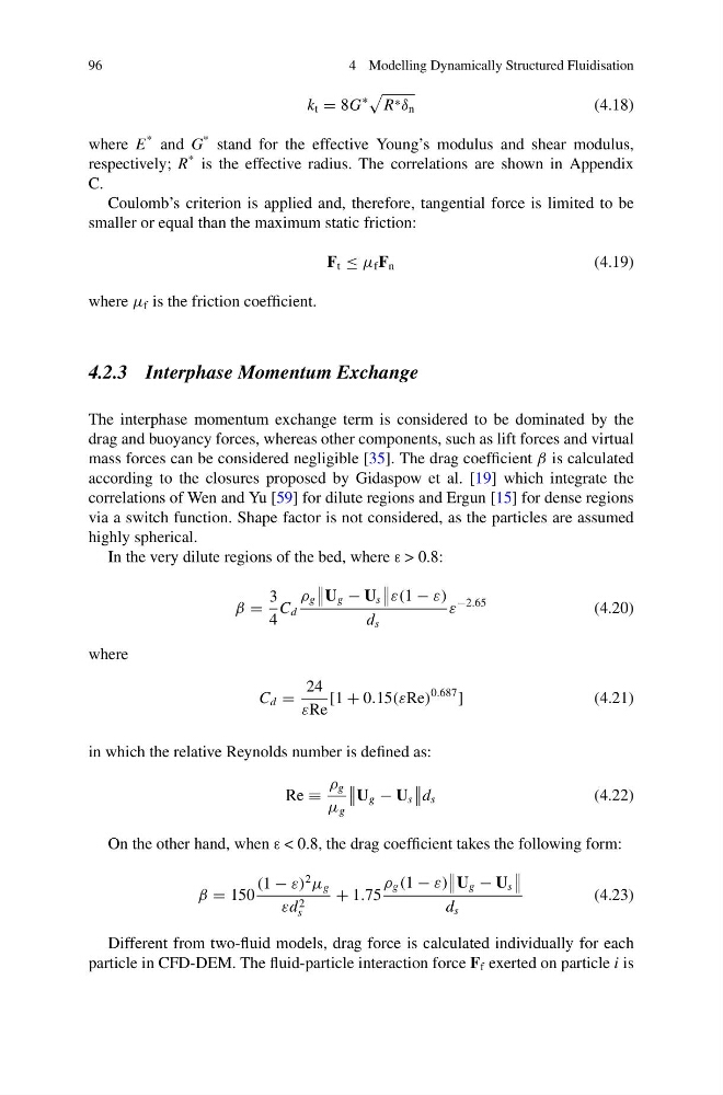
4.2.3 Interphase Momentum Exchange
The interphase momentum exchange term is considered to be dominated by the
drag and buoyancy forces, whereas other components, such as lift forces and virtual
mass forces can be considered negligible [35]. The drag coefficient β is calculated
according to the closures proposed by Gidaspow et al. [19] which integrate the
correlations of Wen and Yu [59] for dilute regions and Ergun [15] for dense regions
via a switch function. Shape factor is not considered, as the particles are assumed
highly spherical.
In the very dilute regions of the bed, where ε > 0.8:
β =
3
4
C d
ρ g
U g − U s
ε(1 − ε)
d s
ε
−2.65
(4.20)
where
C d =
24
εRe
[1 + 0.15(εRe)
0.687
]
(4.21)
in which the relative Reynolds number is defined as:
Re ≡
ρ g
μ g
U g − U s
d s
(4.22)
On the other hand, when ε < 0.8, the drag coefficient takes the following form:
β = 150
(1 − ε)
2
μ g
εd 2
s
+ 1.75
ρ g (1 − ε)
U g − U s
d s
(4.23)
Different from two-fluid models, drag force is calculated individually for each
particle in CFD-DEM. The fluid-particle interaction force F f exerted on particle i is
4 Modelling Dynamically Structured Fluidisation
k t = 8G
∗
R ∗ δ n
(4.18)
where E
* and G
* stand for the effective Young’s modulus and shear modulus,
respectively; R
* is the effective radius. The correlations are shown in Appendix
C.
Coulomb’s criterion is applied and, therefore, tangential force is limited to be
smaller or equal than the maximum static friction:
F t ≤ μ f F n
(4.19)
where μ f is the friction coefficient.
4.2.3 Interphase Momentum Exchange
The interphase momentum exchange term is considered to be dominated by the
drag and buoyancy forces, whereas other components, such as lift forces and virtual
mass forces can be considered negligible [35]. The drag coefficient β is calculated
according to the closures proposed by Gidaspow et al. [19] which integrate the
correlations of Wen and Yu [59] for dilute regions and Ergun [15] for dense regions
via a switch function. Shape factor is not considered, as the particles are assumed
highly spherical.
In the very dilute regions of the bed, where ε > 0.8:
β =
3
4
C d
ρ g
U g − U s
ε(1 − ε)
d s
ε
−2.65
(4.20)
where
C d =
24
εRe
[1 + 0.15(εRe)
0.687
]
(4.21)
in which the relative Reynolds number is defined as:
Re ≡
ρ g
μ g
U g − U s
d s
(4.22)
On the other hand, when ε < 0.8, the drag coefficient takes the following form:
β = 150
(1 − ε)
2
μ g
εd 2
s
+ 1.75
ρ g (1 − ε)
U g − U s
d s
(4.23)
Different from two-fluid models, drag force is calculated individually for each
particle in CFD-DEM. The fluid-particle interaction force F f exerted on particle i is