

3.8.5 Choosing the Correct Cooling Tower
As previously mentioned, the Internet offers a window to a wide source of technical
information. As information is readily found on the World Wide Web, this chapter
will not direct readers to specific sites for design advice. Using several search
engines with proper key phrases will return several excellent results to consult
regarding a cooling tower project. The basic data to gather at the start of such a
project [25] are:
1. The heat load on the tower
2. Range (temperature difference of water in vs. water out)
3. Approach (temperature difference water leaving vs. air entering wet bulb
temperature)
4. Approximate tower size
As can be seen, if Items 1–3 are known, one will be ready to consult with the
engineering staffs of potential suppliers of a cooling tower to determine Item 4.
If the wet bulb temperature is not known, a quick estimate can be made by
dipping a thermometer into the water and then reading the lowest temperature the
thermometer registers as the water evaporates. This temperature is the wet bulb
temperature. Several readings in the environmental conditions for which the cooling
tower is proposed should be taken. Pertinent articles regarding cooling tower design
[26] frequently appear in various trade magazines as well.
3.8.6 St. Johns River Power Park [27]
This 632,000 KW coal-fired electric power plant is jointly own by JEA and Florida
Power Light. It is located in Jacksonville, Florida. Phase constructed was started in
the 1980s and completed in 1988. Initially, the plant is equipment emission control
units which include NOx burners, electrostatic precipitators, and wet limestone flue
gas de-sulfurization units. A di-basic acid injection system to enhance SO 2 removal
and selective catalytic reactors to further reduce NOx emissions was added in
204 and 2009, respectively. The facility has two hyperbolic-shaped cooling towers
with fill (packing) each 460 feet high with base diameter of 370 feet. The cooling
towers are equipment with bottom and top drift eliminators. The design criteria for
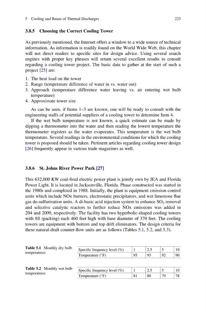
these natural-draft counter-flow units are as follows (Tables 5.1, 5.2, and 5.3).
Table 5.1 Monthly dry bulb
temperatures
Specific frequency level (%)
1
2.5
5
10
Temperature (
F)
95
93
92
90
Table 5.2 Monthly wet bulb
temperatures
Specific frequency level (%)
1
2.5
5
10
Temperature (
F)
81
80
79
78
5 Cooling and Reuse of Thermal Discharges
223
As previously mentioned, the Internet offers a window to a wide source of technical
information. As information is readily found on the World Wide Web, this chapter
will not direct readers to specific sites for design advice. Using several search
engines with proper key phrases will return several excellent results to consult
regarding a cooling tower project. The basic data to gather at the start of such a
project [25] are:
1. The heat load on the tower
2. Range (temperature difference of water in vs. water out)
3. Approach (temperature difference water leaving vs. air entering wet bulb
temperature)
4. Approximate tower size
As can be seen, if Items 1–3 are known, one will be ready to consult with the
engineering staffs of potential suppliers of a cooling tower to determine Item 4.
If the wet bulb temperature is not known, a quick estimate can be made by
dipping a thermometer into the water and then reading the lowest temperature the
thermometer registers as the water evaporates. This temperature is the wet bulb
temperature. Several readings in the environmental conditions for which the cooling
tower is proposed should be taken. Pertinent articles regarding cooling tower design
[26] frequently appear in various trade magazines as well.
3.8.6 St. Johns River Power Park [27]
This 632,000 KW coal-fired electric power plant is jointly own by JEA and Florida
Power Light. It is located in Jacksonville, Florida. Phase constructed was started in
the 1980s and completed in 1988. Initially, the plant is equipment emission control
units which include NOx burners, electrostatic precipitators, and wet limestone flue
gas de-sulfurization units. A di-basic acid injection system to enhance SO 2 removal
and selective catalytic reactors to further reduce NOx emissions was added in
204 and 2009, respectively. The facility has two hyperbolic-shaped cooling towers
with fill (packing) each 460 feet high with base diameter of 370 feet. The cooling
towers are equipment with bottom and top drift eliminators. The design criteria for
these natural-draft counter-flow units are as follows (Tables 5.1, 5.2, and 5.3).
Table 5.1 Monthly dry bulb
temperatures
Specific frequency level (%)
1
2.5
5
10
Temperature (
F)
95
93
92
90
Table 5.2 Monthly wet bulb
temperatures
Specific frequency level (%)
1
2.5
5
10
Temperature (
F)
81
80
79
78
5 Cooling and Reuse of Thermal Discharges
223