

3.3 Natural Draft Atmospheric Cooling Towers
The flow scheme for this design of cooling tower is presented in Fig. 5.5. Air enters
the tower through open louvers on the sides of the tower. As the air passes through
the tower, it comes in contact with water that is sprayed downward in the tower.
Wind currents primarily drive the horizontal airflow through the tower. Such towers
are sometimes open, containing only the falling water spray.
Crossflow Natural Draft Tower
Fall
Canopy
Air Outlet
Air
Inlet
Air
Inlet
Water
Outlet
Water
Inlet
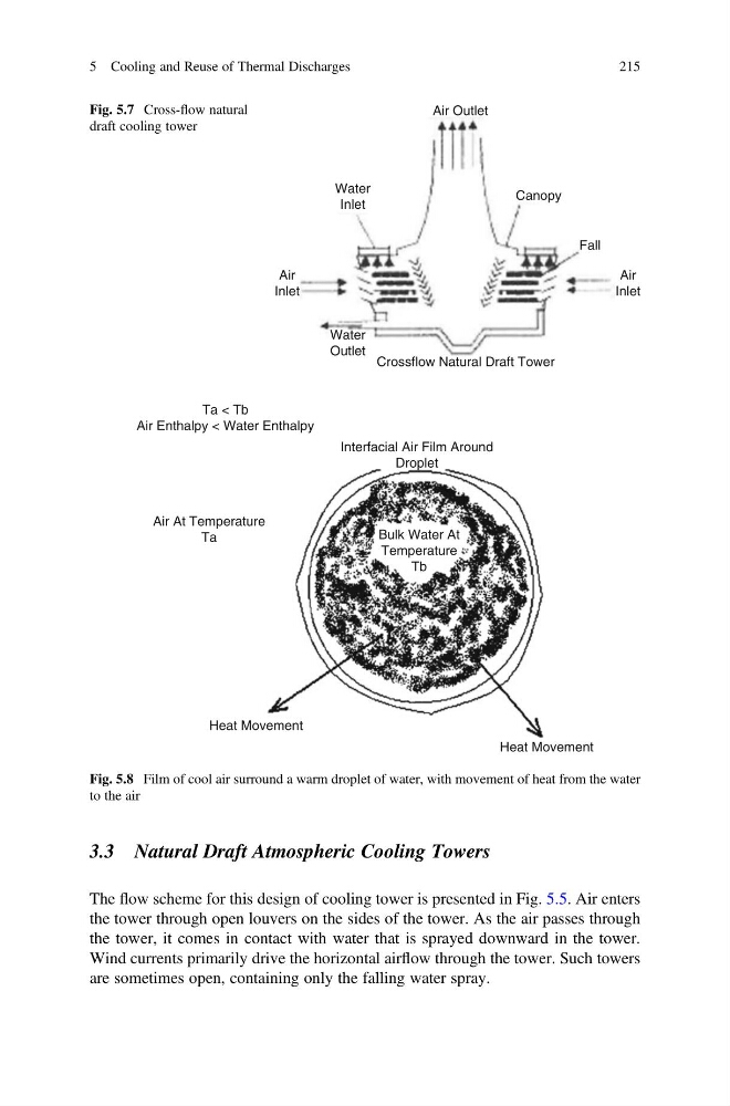
Fig. 5.7 Cross-flow natural
draft cooling tower
Heat Movement
Air At Temperature
Ta
Bulk Water At
Temperature
Tb
Ta < Tb
Air Enthalpy < Water Enthalpy
Heat Movement
Interfacial Air Film Around
Droplet
Fig. 5.8 Film of cool air surround a warm droplet of water, with movement of heat from the water
to the air
5 Cooling and Reuse of Thermal Discharges
215
The flow scheme for this design of cooling tower is presented in Fig. 5.5. Air enters
the tower through open louvers on the sides of the tower. As the air passes through
the tower, it comes in contact with water that is sprayed downward in the tower.
Wind currents primarily drive the horizontal airflow through the tower. Such towers
are sometimes open, containing only the falling water spray.
Crossflow Natural Draft Tower
Fall
Canopy
Air Outlet
Air
Inlet
Air
Inlet
Water
Outlet
Water
Inlet
Fig. 5.7 Cross-flow natural
draft cooling tower
Heat Movement
Air At Temperature
Ta
Bulk Water At
Temperature
Tb
Ta < Tb
Air Enthalpy < Water Enthalpy
Heat Movement
Interfacial Air Film Around
Droplet
Fig. 5.8 Film of cool air surround a warm droplet of water, with movement of heat from the water
to the air
5 Cooling and Reuse of Thermal Discharges
215