

Induced (also called mechanical) draft towers employ a fan to move air through
the tower. Natural draft towers rely upon the difference in density between the warm
air exiting a tower and the cool air inside the tower to act as the driving force for air
movement. Most towers at large industrial locations have direct contact between air
and water and are hence considered to be “wet” towers. Some towers, however, are
designed to keep the air and water separate and hence are considered to be “dry”
towers.
Dry cooling towers are used in specialized applications where temperatures are
very high. Convection is the primary mechanism of heat transfer. Since dry towers
are markedly less efficient than wet towers, they are not discussed at length here.
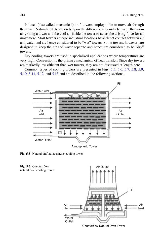
Common types of cooling towers are presented in Figs. 5.5, 5.6, 5.7, 5.8, 5.9,
5.10, 5.11, 5.12, and 5.13 and are described in the following sections.
Water Outlet
Water Inlet
Fill
Air
Inlet
Air
Outlet
Atmospheric Tower
Fig. 5.5 Natural draft atmospheric cooling tower
Fill
Air Outlet
Air
Inlet
Air
Inlet
Water
Outlet
Counterflow Natural Draft Tower
Fig. 5.6 Counter-flow
natural draft cooling tower
214
Y.-T. Hung et al.
the tower. Natural draft towers rely upon the difference in density between the warm
air exiting a tower and the cool air inside the tower to act as the driving force for air
movement. Most towers at large industrial locations have direct contact between air
and water and are hence considered to be “wet” towers. Some towers, however, are
designed to keep the air and water separate and hence are considered to be “dry”
towers.
Dry cooling towers are used in specialized applications where temperatures are
very high. Convection is the primary mechanism of heat transfer. Since dry towers
are markedly less efficient than wet towers, they are not discussed at length here.
Common types of cooling towers are presented in Figs. 5.5, 5.6, 5.7, 5.8, 5.9,
5.10, 5.11, 5.12, and 5.13 and are described in the following sections.
Water Outlet
Water Inlet
Fill
Air
Inlet
Air
Outlet
Atmospheric Tower
Fig. 5.5 Natural draft atmospheric cooling tower
Fill
Air Outlet
Air
Inlet
Air
Inlet
Water
Outlet
Counterflow Natural Draft Tower
Fig. 5.6 Counter-flow
natural draft cooling tower
214
Y.-T. Hung et al.