

22
Ò. Iglesias and H. Kachkachi
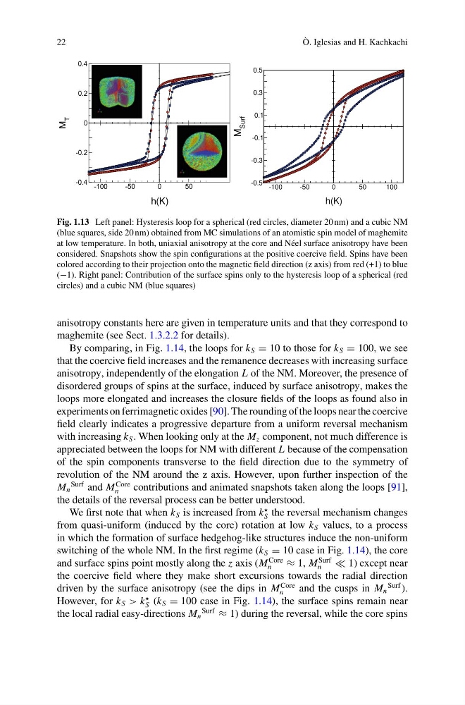
Fig. 1.13 Left panel: Hysteresis loop for a spherical (red circles, diameter 20 nm) and a cubic NM
(blue squares, side 20 nm) obtained from MC simulations of an atomistic spin model of maghemite
at low temperature. In both, uniaxial anisotropy at the core and Néel surface anisotropy have been
considered. Snapshots show the spin configurations at the positive coercive field. Spins have been
colored according to their projection onto the magnetic field direction (z axis) from red (+1) to blue
(−1). Right panel: Contribution of the surface spins only to the hysteresis loop of a spherical (red
circles) and a cubic NM (blue squares)
anisotropy constants here are given in temperature units and that they correspond to
maghemite (see Sect. 1.3.2.2 for details).
By comparing, in Fig. 1.14, the loops for k S = 10 to those for k S = 100, we see
that the coercive field increases and the remanence decreases with increasing surface
anisotropy, independently of the elongation L of the NM. Moreover, the presence of
disordered groups of spins at the surface, induced by surface anisotropy, makes the
loops more elongated and increases the closure fields of the loops as found also in
experiments on ferrimagnetic oxides [90]. The rounding of the loops near the coercive
field clearly indicates a progressive departure from a uniform reversal mechanism
with increasing k S . When looking only at the M z component, not much difference is
appreciated between the loops for NM with different L because of the compensation
of the spin components transverse to the field direction due to the symmetry of
revolution of the NM around the z axis. However, upon further inspection of the
M n
Surf and M
Core
n
contributions and animated snapshots taken along the loops [91],
the details of the reversal process can be better understood.
We first note that when k S is increased from k
S the reversal mechanism changes
from quasi-uniform (induced by the core) rotation at low k S values, to a process
in which the formation of surface hedgehog-like structures induce the non-uniform
switching of the whole NM. In the first regime (k S = 10 case in Fig. 1.14), the core
and surface spins point mostly along the z axis (M
Core
n
≈ 1, M
Surf
n
1) except near
the coercive field where they make short excursions towards the radial direction
driven by the surface anisotropy (see the dips in M
Core
n
and the cusps in M n
Surf ).
However, for k S > k
S (k S = 100 case in Fig. 1.14), the surface spins remain near
the local radial easy-directions M n
Surf
≈ 1) during the reversal, while the core spins
Ò. Iglesias and H. Kachkachi
Fig. 1.13 Left panel: Hysteresis loop for a spherical (red circles, diameter 20 nm) and a cubic NM
(blue squares, side 20 nm) obtained from MC simulations of an atomistic spin model of maghemite
at low temperature. In both, uniaxial anisotropy at the core and Néel surface anisotropy have been
considered. Snapshots show the spin configurations at the positive coercive field. Spins have been
colored according to their projection onto the magnetic field direction (z axis) from red (+1) to blue
(−1). Right panel: Contribution of the surface spins only to the hysteresis loop of a spherical (red
circles) and a cubic NM (blue squares)
anisotropy constants here are given in temperature units and that they correspond to
maghemite (see Sect. 1.3.2.2 for details).
By comparing, in Fig. 1.14, the loops for k S = 10 to those for k S = 100, we see
that the coercive field increases and the remanence decreases with increasing surface
anisotropy, independently of the elongation L of the NM. Moreover, the presence of
disordered groups of spins at the surface, induced by surface anisotropy, makes the
loops more elongated and increases the closure fields of the loops as found also in
experiments on ferrimagnetic oxides [90]. The rounding of the loops near the coercive
field clearly indicates a progressive departure from a uniform reversal mechanism
with increasing k S . When looking only at the M z component, not much difference is
appreciated between the loops for NM with different L because of the compensation
of the spin components transverse to the field direction due to the symmetry of
revolution of the NM around the z axis. However, upon further inspection of the
M n
Surf and M
Core
n
contributions and animated snapshots taken along the loops [91],
the details of the reversal process can be better understood.
We first note that when k S is increased from k
S the reversal mechanism changes
from quasi-uniform (induced by the core) rotation at low k S values, to a process
in which the formation of surface hedgehog-like structures induce the non-uniform
switching of the whole NM. In the first regime (k S = 10 case in Fig. 1.14), the core
and surface spins point mostly along the z axis (M
Core
n
≈ 1, M
Surf
n
1) except near
the coercive field where they make short excursions towards the radial direction
driven by the surface anisotropy (see the dips in M
Core
n
and the cusps in M n
Surf ).
However, for k S > k
S (k S = 100 case in Fig. 1.14), the surface spins remain near
the local radial easy-directions M n
Surf
≈ 1) during the reversal, while the core spins