

200
S. Izawa
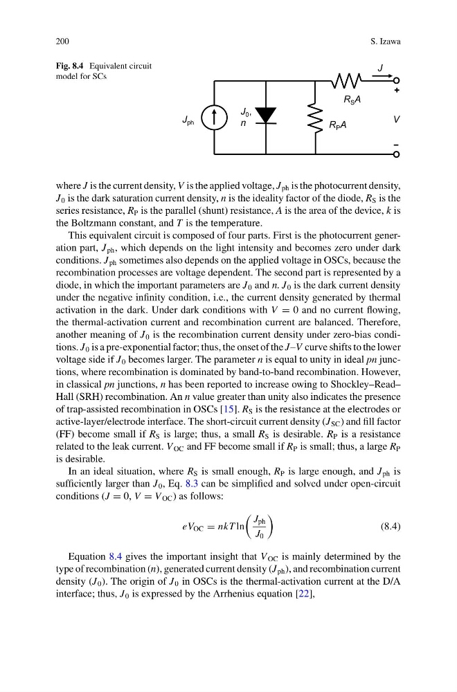
Fig. 8.4 Equivalent circuit
model for SCs
J ph
J 0 ,
n
J
V
R S A
R P A
where J is the current density, V is the applied voltage, J ph is the photocurrent density,
J 0 is the dark saturation current density, n is the ideality factor of the diode, R S is the
series resistance, R P is the parallel (shunt) resistance, A is the area of the device, k is
the Boltzmann constant, and T is the temperature.
This equivalent circuit is composed of four parts. First is the photocurrent generation part, J ph , which depends on the light intensity and becomes zero under dark
conditions. J ph sometimes also depends on the applied voltage in OSCs, because the
recombination processes are voltage dependent. The second part is represented by a
diode, in which the important parameters are J 0 and n. J 0 is the dark current density
under the negative infinity condition, i.e., the current density generated by thermal
activation in the dark. Under dark conditions with V = 0 and no current flowing,
the thermal-activation current and recombination current are balanced. Therefore,
another meaning of J 0 is the recombination current density under zero-bias conditions. J 0 is a pre-exponential factor; thus, the onset of the J–V curve shifts to the lower
voltage side if J 0 becomes larger. The parameter n is equal to unity in ideal pn junctions, where recombination is dominated by band-to-band recombination. However,
in classical pn junctions, n has been reported to increase owing to Shockley–Read–
Hall (SRH) recombination. An n value greater than unity also indicates the presence
of trap-assisted recombination in OSCs [15]. R S is the resistance at the electrodes or
active-layer/electrode interface. The short-circuit current density (J SC ) and fill factor
(FF) become small if R S is large; thus, a small R S is desirable. R P is a resistance
related to the leak current. V OC and FF become small if R P is small; thus, a large R P
is desirable.
In an ideal situation, where R S is small enough, R P is large enough, and J ph is
sufficiently larger than J 0 , Eq. 8.3 can be simplified and solved under open-circuit
conditions (J = 0, V = V OC ) as follows:
eV OC = nkT ln
J ph
J 0
(8.4)
Equation 8.4 gives the important insight that V OC is mainly determined by the
type of recombination (n), generated current density (J ph ), and recombination current
density (J 0 ). The origin of J 0 in OSCs is the thermal-activation current at the D/A
interface; thus, J 0 is expressed by the Arrhenius equation [22],
S. Izawa
Fig. 8.4 Equivalent circuit
model for SCs
J ph
J 0 ,
n
J
V
R S A
R P A
where J is the current density, V is the applied voltage, J ph is the photocurrent density,
J 0 is the dark saturation current density, n is the ideality factor of the diode, R S is the
series resistance, R P is the parallel (shunt) resistance, A is the area of the device, k is
the Boltzmann constant, and T is the temperature.
This equivalent circuit is composed of four parts. First is the photocurrent generation part, J ph , which depends on the light intensity and becomes zero under dark
conditions. J ph sometimes also depends on the applied voltage in OSCs, because the
recombination processes are voltage dependent. The second part is represented by a
diode, in which the important parameters are J 0 and n. J 0 is the dark current density
under the negative infinity condition, i.e., the current density generated by thermal
activation in the dark. Under dark conditions with V = 0 and no current flowing,
the thermal-activation current and recombination current are balanced. Therefore,
another meaning of J 0 is the recombination current density under zero-bias conditions. J 0 is a pre-exponential factor; thus, the onset of the J–V curve shifts to the lower
voltage side if J 0 becomes larger. The parameter n is equal to unity in ideal pn junctions, where recombination is dominated by band-to-band recombination. However,
in classical pn junctions, n has been reported to increase owing to Shockley–Read–
Hall (SRH) recombination. An n value greater than unity also indicates the presence
of trap-assisted recombination in OSCs [15]. R S is the resistance at the electrodes or
active-layer/electrode interface. The short-circuit current density (J SC ) and fill factor
(FF) become small if R S is large; thus, a small R S is desirable. R P is a resistance
related to the leak current. V OC and FF become small if R P is small; thus, a large R P
is desirable.
In an ideal situation, where R S is small enough, R P is large enough, and J ph is
sufficiently larger than J 0 , Eq. 8.3 can be simplified and solved under open-circuit
conditions (J = 0, V = V OC ) as follows:
eV OC = nkT ln
J ph
J 0
(8.4)
Equation 8.4 gives the important insight that V OC is mainly determined by the
type of recombination (n), generated current density (J ph ), and recombination current
density (J 0 ). The origin of J 0 in OSCs is the thermal-activation current at the D/A
interface; thus, J 0 is expressed by the Arrhenius equation [22],