

1 Basic Principles of Modern Organic Solar Cells
13
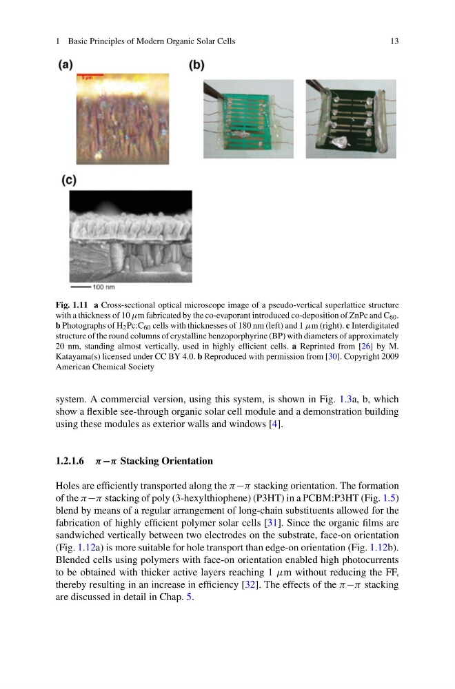
Fig. 1.11 a Cross-sectional optical microscope image of a pseudo-vertical superlattice structure
with a thickness of 10 μm fabricated by the co-evaporant introduced co-deposition of ZnPc and C 60 .
b Photographs of H 2 Pc:C 60 cells with thicknesses of 180 nm (left) and 1 μm (right). c Interdigitated
structure of the round columns of crystalline benzoporphyrine (BP) with diameters of approximately
20 nm, standing almost vertically, used in highly efficient cells. a Reprinted from [26] by M.
Katayama(s) licensed under CC BY 4.0. b Reproduced with permission from [30]. Copyright 2009
American Chemical Society
system. A commercial version, using this system, is shown in Fig. 1.3a, b, which
show a flexible see-through organic solar cell module and a demonstration building
using these modules as exterior walls and windows [4].
1.2.1.6 π −π Stacking Orientation
Holes are efficiently transported along the π −π stacking orientation. The formation
of the π −π stacking of poly (3-hexylthiophene) (P3HT) in a PCBM:P3HT (Fig. 1.5)
blend by means of a regular arrangement of long-chain substituents allowed for the
fabrication of highly efficient polymer solar cells [31]. Since the organic films are
sandwiched vertically between two electrodes on the substrate, face-on orientation
(Fig. 1.12a) is more suitable for hole transport than edge-on orientation (Fig. 1.12b).
Blended cells using polymers with face-on orientation enabled high photocurrents
to be obtained with thicker active layers reaching 1 μm without reducing the FF,
thereby resulting in an increase in efficiency [32]. The effects of the π −π stacking
are discussed in detail in Chap. 5.
13
Fig. 1.11 a Cross-sectional optical microscope image of a pseudo-vertical superlattice structure
with a thickness of 10 μm fabricated by the co-evaporant introduced co-deposition of ZnPc and C 60 .
b Photographs of H 2 Pc:C 60 cells with thicknesses of 180 nm (left) and 1 μm (right). c Interdigitated
structure of the round columns of crystalline benzoporphyrine (BP) with diameters of approximately
20 nm, standing almost vertically, used in highly efficient cells. a Reprinted from [26] by M.
Katayama(s) licensed under CC BY 4.0. b Reproduced with permission from [30]. Copyright 2009
American Chemical Society
system. A commercial version, using this system, is shown in Fig. 1.3a, b, which
show a flexible see-through organic solar cell module and a demonstration building
using these modules as exterior walls and windows [4].
1.2.1.6 π −π Stacking Orientation
Holes are efficiently transported along the π −π stacking orientation. The formation
of the π −π stacking of poly (3-hexylthiophene) (P3HT) in a PCBM:P3HT (Fig. 1.5)
blend by means of a regular arrangement of long-chain substituents allowed for the
fabrication of highly efficient polymer solar cells [31]. Since the organic films are
sandwiched vertically between two electrodes on the substrate, face-on orientation
(Fig. 1.12a) is more suitable for hole transport than edge-on orientation (Fig. 1.12b).
Blended cells using polymers with face-on orientation enabled high photocurrents
to be obtained with thicker active layers reaching 1 μm without reducing the FF,
thereby resulting in an increase in efficiency [32]. The effects of the π −π stacking
are discussed in detail in Chap. 5.