

and nickel have been electrodeposited using the ‘nanochannel’ glass membranes.
Other templates that have been reported include synthetic lipids, peptides and
mesoporous molecular sieves [84–88].
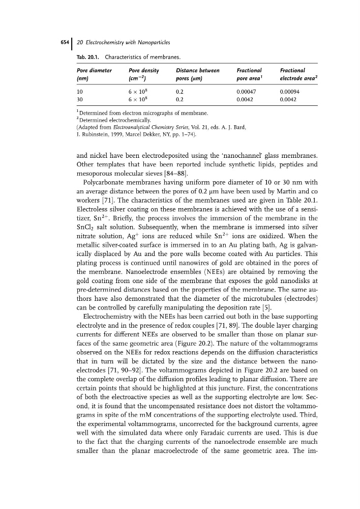
Polycarbonate membranes having uniform pore diameter of 10 or 30 nm with
an average distance between the pores of 0.2 mm have been used by Martin and co
workers [71]. The characteristics of the membranes used are given in Table 20.1.
Electroless silver coating on these membranes is achieved with the use of a sensitizer, Sn
2þ . Briefly, the process involves the immersion of the membrane in the
SnCl 2 salt solution. Subsequently, when the membrane is immersed into silver
nitrate solution, Ag
þ ions are reduced while Sn
2þ ions are oxidized. When the
metallic silver-coated surface is immersed in to an Au plating bath, Ag is galvanically displaced by Au and the pore walls become coated with Au particles. This
plating process is continued until nanowires of gold are obtained in the pores of
the membrane. Nanoelectrode ensembles (NEEs) are obtained by removing the
gold coating from one side of the membrane that exposes the gold nanodisks at
pre-determined distances based on the properties of the membrane. The same authors have also demonstrated that the diameter of the microtubules (electrodes)
can be controlled by carefully manipulating the deposition rate [5].
Electrochemistry with the NEEs has been carried out both in the base supporting
electrolyte and in the presence of redox couples [71, 89]. The double layer charging
currents for different NEEs are observed to be smaller than those on planar surfaces of the same geometric area (Figure 20.2). The nature of the voltammograms
observed on the NEEs for redox reactions depends on the diffusion characteristics
that in turn will be dictated by the size and the distance between the nanoelectrodes [71, 90–92]. The voltammograms depicted in Figure 20.2 are based on
the complete overlap of the diffusion profiles leading to planar diffusion. There are
certain points that should be highlighted at this juncture. First, the concentrations
of both the electroactive species as well as the supporting electrolyte are low. Second, it is found that the uncompensated resistance does not distort the voltammograms in spite of the mM concentrations of the supporting electrolyte used. Third,
the experimental voltammograms, uncorrected for the background currents, agree
well with the simulated data where only Faradaic currents are used. This is due
to the fact that the charging currents of the nanoelectrode ensemble are much
smaller than the planar macroelectrode of the same geometric area. The imTab. 20.1. Characteristics of membranes.
Pore diameter
(nm)
Pore density
(cm
C2 )
Distance between
pores (mm)
Fractional
pore area
1
Fractional
electrode area
2
10
6 Â 10
8
0.2
0.00047
0.00094
30
6 Â 10
8
0.2
0.0042
0.0042
1 Determined from electron micrographs of membrane.
2 Determined electrochemically.
(Adapted from Electroanalytical Chemistry Series, Vol. 21, eds. A. J. Bard,
I. Rubinstein, 1999, Marcel Dekker, NY, pp. 1–74).
20 Electrochemistry with Nanoparticles
654