

phosphine ligand. These NiaTe distances vary from 2.45 to 2.90 A ˚ , and can be
contrasted with the shorter nickel–selenium distances observed in 2 (2.30–2.48 A ˚ ).
The success of this synthetic approach for the delivery of ‘‘Te(0)’’ to the metal
centers requires the presence of additional PEt 3 in the reaction solutions, in
order to circumvent the deposition of tellurium metal from the facile reduction
of R 3 PbTe to R 3 P (R 3 PbTe Ð R 3 P þ Te) [17]. In contrast, metal-sulfide clusters
are generally not accessible from trialklyphosphine sulfides, due to the inherent
strength of PbS bonds, unless more forcing conditions are used [22, 23].
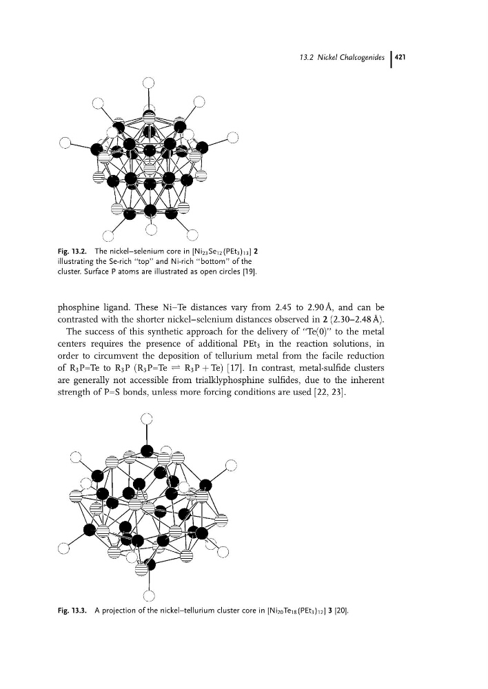
Fig. 13.2. The nickel–selenium core in [Ni 23 Se 12 (PEt 3 ) 13 ] 2
illustrating the Se-rich ‘‘top’’ and Ni-rich ‘‘bottom’’ of the
cluster. Surface P atoms are illustrated as open circles [19].
Fig. 13.3. A projection of the nickel–tellurium cluster core in [Ni 20 Te 18 (PEt 3 ) 12 ] 3 [20].
13.2 Nickel Chalcogenides 421
contrasted with the shorter nickel–selenium distances observed in 2 (2.30–2.48 A ˚ ).
The success of this synthetic approach for the delivery of ‘‘Te(0)’’ to the metal
centers requires the presence of additional PEt 3 in the reaction solutions, in
order to circumvent the deposition of tellurium metal from the facile reduction
of R 3 PbTe to R 3 P (R 3 PbTe Ð R 3 P þ Te) [17]. In contrast, metal-sulfide clusters
are generally not accessible from trialklyphosphine sulfides, due to the inherent
strength of PbS bonds, unless more forcing conditions are used [22, 23].
Fig. 13.2. The nickel–selenium core in [Ni 23 Se 12 (PEt 3 ) 13 ] 2
illustrating the Se-rich ‘‘top’’ and Ni-rich ‘‘bottom’’ of the
cluster. Surface P atoms are illustrated as open circles [19].
Fig. 13.3. A projection of the nickel–tellurium cluster core in [Ni 20 Te 18 (PEt 3 ) 12 ] 3 [20].
13.2 Nickel Chalcogenides 421