

rate in certain crystallographic directions is enhanced not only by existing dislocations in the growth direction but also by the formation of facets with a low
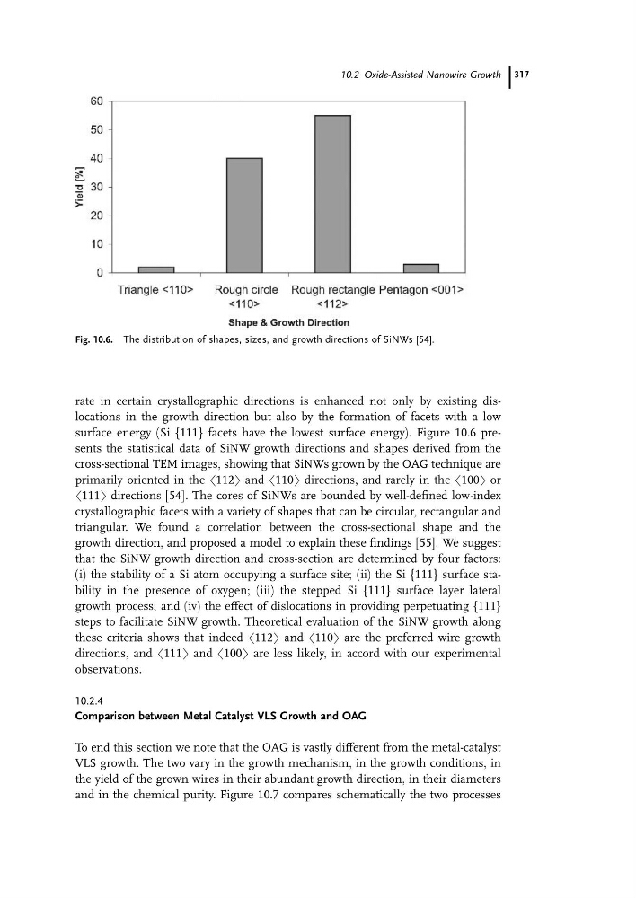
surface energy (Si {111} facets have the lowest surface energy). Figure 10.6 presents the statistical data of SiNW growth directions and shapes derived from the
cross-sectional TEM images, showing that SiNWs grown by the OAG technique are
primarily oriented in the h112i and h110i directions, and rarely in the h100i or
h111i directions [54]. The cores of SiNWs are bounded by well-defined low-index
crystallographic facets with a variety of shapes that can be circular, rectangular and
triangular. We found a correlation between the cross-sectional shape and the
growth direction, and proposed a model to explain these findings [55]. We suggest
that the SiNW growth direction and cross-section are determined by four factors:
(i) the stability of a Si atom occupying a surface site; (ii) the Si {111} surface stability in the presence of oxygen; (iii) the stepped Si {111} surface layer lateral
growth process; and (iv) the effect of dislocations in providing perpetuating {111}
steps to facilitate SiNW growth. Theoretical evaluation of the SiNW growth along
these criteria shows that indeed h112i and h110i are the preferred wire growth
directions, and h111i and h100i are less likely, in accord with our experimental
observations.
10.2.4
Comparison between Metal Catalyst VLS Growth and OAG
To end this section we note that the OAG is vastly different from the metal-catalyst
VLS growth. The two vary in the growth mechanism, in the growth conditions, in
the yield of the grown wires in their abundant growth direction, in their diameters
and in the chemical purity. Figure 10.7 compares schematically the two processes
Fig. 10.6. The distribution of shapes, sizes, and growth directions of SiNWs [54].
10.2 Oxide-Assisted Nanowire Growth 317
surface energy (Si {111} facets have the lowest surface energy). Figure 10.6 presents the statistical data of SiNW growth directions and shapes derived from the
cross-sectional TEM images, showing that SiNWs grown by the OAG technique are
primarily oriented in the h112i and h110i directions, and rarely in the h100i or
h111i directions [54]. The cores of SiNWs are bounded by well-defined low-index
crystallographic facets with a variety of shapes that can be circular, rectangular and
triangular. We found a correlation between the cross-sectional shape and the
growth direction, and proposed a model to explain these findings [55]. We suggest
that the SiNW growth direction and cross-section are determined by four factors:
(i) the stability of a Si atom occupying a surface site; (ii) the Si {111} surface stability in the presence of oxygen; (iii) the stepped Si {111} surface layer lateral
growth process; and (iv) the effect of dislocations in providing perpetuating {111}
steps to facilitate SiNW growth. Theoretical evaluation of the SiNW growth along
these criteria shows that indeed h112i and h110i are the preferred wire growth
directions, and h111i and h100i are less likely, in accord with our experimental
observations.
10.2.4
Comparison between Metal Catalyst VLS Growth and OAG
To end this section we note that the OAG is vastly different from the metal-catalyst
VLS growth. The two vary in the growth mechanism, in the growth conditions, in
the yield of the grown wires in their abundant growth direction, in their diameters
and in the chemical purity. Figure 10.7 compares schematically the two processes
Fig. 10.6. The distribution of shapes, sizes, and growth directions of SiNWs [54].
10.2 Oxide-Assisted Nanowire Growth 317