

we show TEM images of these nanotubes. These HfS 2 nanotubes are obtained in
good yield by the decomposition of HfS 3 [234]. The HREM image in Figure 8.23(d)
shows a considerable number of defects and edge dislocations present along the
length of the tube wall. The analysis of the electron diffraction (ED) pattern together with the HREM indicates that the growth axis of the nanotube is perpendicular to the c-direction.
Exhaustive studies have been carried out on the synthesis of BN nanotubes and
nanowires by various CVD techniques [225]. The methods examined include heating boric acid with activated carbon, multi-walled carbon nanotubes, catalytic iron
particles or a mixture of activated carbon and iron particles, in the presence of
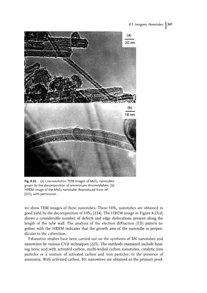
ammonia. With activated carbon, BN nanowires are obtained as the primary prodFig. 8.22. (a) Low-resolution TEM images of MoS 2 nanotubes
grown by the decomposition of ammonium thiomolybdate; (b)
HREM image of the MoS 2 nanotube. Reproduced from ref.
[231], with permission.
8.3 Inorganic Nanotubes 247
good yield by the decomposition of HfS 3 [234]. The HREM image in Figure 8.23(d)
shows a considerable number of defects and edge dislocations present along the
length of the tube wall. The analysis of the electron diffraction (ED) pattern together with the HREM indicates that the growth axis of the nanotube is perpendicular to the c-direction.
Exhaustive studies have been carried out on the synthesis of BN nanotubes and
nanowires by various CVD techniques [225]. The methods examined include heating boric acid with activated carbon, multi-walled carbon nanotubes, catalytic iron
particles or a mixture of activated carbon and iron particles, in the presence of
ammonia. With activated carbon, BN nanowires are obtained as the primary prodFig. 8.22. (a) Low-resolution TEM images of MoS 2 nanotubes
grown by the decomposition of ammonium thiomolybdate; (b)
HREM image of the MoS 2 nanotube. Reproduced from ref.
[231], with permission.
8.3 Inorganic Nanotubes 247