

44
2 Optical Fiber Structures and Light Guiding Principles
The corresponding fraction of optical power that traverses the material interface
is given by the transmittance T
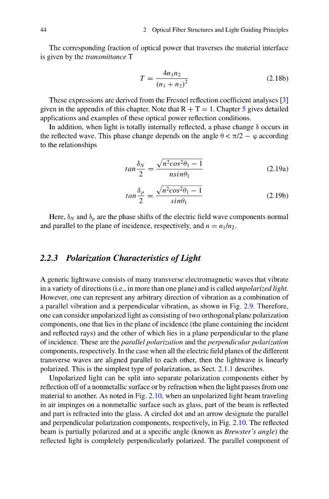
T =
4n 1 n 2
(n 1 + n 2 )
2
(2.18b)
These expressions are derived from the Fresnel reflection coefficient analyses [3]
given in the appendix of this chapter. Note that R + T = 1. Chapter 5 gives detailed
applications and examples of these optical power reflection conditions.
In addition, when light is totally internally reflected, a phase change δ occurs in
the reflected wave. This phase change depends on the angle θ < π/2 − ϕ according
to the relationships
tan
δ N
2
=
n 2 cos 2 θ 1 − 1
nsinθ 1
(2.19a)
tan
δ p
2
=
n 2 cos 2 θ 1 − 1
sinθ 1
(2.19b)
Here, δ N and δ p are the phase shifts of the electric field wave components normal
and parallel to the plane of incidence, respectively, and n = n 1 /n 2 .
2.2.3 Polarization Characteristics of Light
A generic lightwave consists of many transverse electromagnetic waves that vibrate
in a variety of directions (i.e., in more than one plane) and is called unpolarized light.
However, one can represent any arbitrary direction of vibration as a combination of
a parallel vibration and a perpendicular vibration, as shown in Fig. 2.9. Therefore,
one can consider unpolarized light as consisting of two orthogonal plane polarization
components, one that lies in the plane of incidence (the plane containing the incident
and reflected rays) and the other of which lies in a plane perpendicular to the plane
of incidence. These are the parallel polarization and the perpendicular polarization
components, respectively. In the case when all the electric field planes of the different
transverse waves are aligned parallel to each other, then the lightwave is linearly
polarized. This is the simplest type of polarization, as Sect. 2.1.1 describes.
Unpolarized light can be split into separate polarization components either by
reflection off of a nonmetallic surface or by refraction when the light passes from one
material to another. As noted in Fig. 2.10, when an unpolarized light beam traveling
in air impinges on a nonmetallic surface such as glass, part of the beam is reflected
and part is refracted into the glass. A circled dot and an arrow designate the parallel
and perpendicular polarization components, respectively, in Fig. 2.10. The reflected
beam is partially polarized and at a specific angle (known as Brewster’s angle) the
reflected light is completely perpendicularly polarized. The parallel component of
2 Optical Fiber Structures and Light Guiding Principles
The corresponding fraction of optical power that traverses the material interface
is given by the transmittance T
T =
4n 1 n 2
(n 1 + n 2 )
2
(2.18b)
These expressions are derived from the Fresnel reflection coefficient analyses [3]
given in the appendix of this chapter. Note that R + T = 1. Chapter 5 gives detailed
applications and examples of these optical power reflection conditions.
In addition, when light is totally internally reflected, a phase change δ occurs in
the reflected wave. This phase change depends on the angle θ < π/2 − ϕ according
to the relationships
tan
δ N
2
=
n 2 cos 2 θ 1 − 1
nsinθ 1
(2.19a)
tan
δ p
2
=
n 2 cos 2 θ 1 − 1
sinθ 1
(2.19b)
Here, δ N and δ p are the phase shifts of the electric field wave components normal
and parallel to the plane of incidence, respectively, and n = n 1 /n 2 .
2.2.3 Polarization Characteristics of Light
A generic lightwave consists of many transverse electromagnetic waves that vibrate
in a variety of directions (i.e., in more than one plane) and is called unpolarized light.
However, one can represent any arbitrary direction of vibration as a combination of
a parallel vibration and a perpendicular vibration, as shown in Fig. 2.9. Therefore,
one can consider unpolarized light as consisting of two orthogonal plane polarization
components, one that lies in the plane of incidence (the plane containing the incident
and reflected rays) and the other of which lies in a plane perpendicular to the plane
of incidence. These are the parallel polarization and the perpendicular polarization
components, respectively. In the case when all the electric field planes of the different
transverse waves are aligned parallel to each other, then the lightwave is linearly
polarized. This is the simplest type of polarization, as Sect. 2.1.1 describes.
Unpolarized light can be split into separate polarization components either by
reflection off of a nonmetallic surface or by refraction when the light passes from one
material to another. As noted in Fig. 2.10, when an unpolarized light beam traveling
in air impinges on a nonmetallic surface such as glass, part of the beam is reflected
and part is refracted into the glass. A circled dot and an arrow designate the parallel
and perpendicular polarization components, respectively, in Fig. 2.10. The reflected
beam is partially polarized and at a specific angle (known as Brewster’s angle) the
reflected light is completely perpendicularly polarized. The parallel component of