

14.4 Characterization of Optical Fibers
589
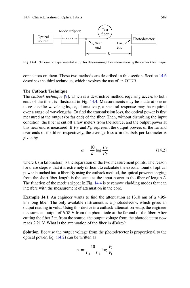
Fig. 14.4 Schematic experimental setup for determining fiber attenuation by the cutback technique
connectors on them. These two methods are described in this section. Section 14.6
describes the third technique, which involves the use of an OTDR.
The Cutback Technique
The cutback technique [9], which is a destructive method requiring access to both
ends of the fiber, is illustrated in Fig. 14.4. Measurements may be made at one or
more specific wavelengths, or, alternatively, a spectral response may be required
over a range of wavelengths. To find the transmission loss, the optical power is first
measured at the output (or far end) of the fiber. Then, without disturbing the input
condition, the fiber is cut off a few meters from the source, and the output power at
this near end is measured. If P F and P N represent the output powers of the far and
near ends of the fiber, respectively, the average loss α in decibels per kilometer is
given by
α =
10
L
log
P N
P F
(14.2)
where L (in kilometers) is the separation of the two measurement points. The reason
for these steps is that it is extremely difficult to calculate the exact amount of optical
power launched into a fiber. By using the cutback method, the optical power emerging
from the short fiber length is the same as the input power to the fiber of length L.
The function of the mode stripper in Fig. 14.4 is to remove cladding modes that can
interfere with the measurement of attenuation in the core.
Example 14.1 An engineer wants to find the attenuation at 1310 nm of a 4.95km long fiber. The only available instrument is a photodetector, which gives an
output reading in volts. Using this device in a cutback-attenuation setup, the engineer
measures an output of 6.58 V from the photodiode at the far end of the fiber. After
cutting the fiber 2 m from the source, the output voltage from the photodetector now
reads 2.21 V. What is the attenuation of the fiber in dB/km?
Solution Because the output voltage from the photodetector is proportional to the
optical power, Eq. (14.2) can be written as
α =
10
L 1 − L 2
log
V 2
V 1