

588
14 Basic Measurement and Monitoring Techniques
the distribution of the light that is refracted sideways out of the core as a function of
the radial position of the laser spot. The variation in the detected optical signal level is
proportional to the index change at the fiber end face. The RIP parameter can be used
to calculate the geometrical parameters of a fiber and to estimate all transmission
properties (e.g., chromatic dispersion and the cut-off wavelength) except attenuation
and polarization-mode dispersion.
14.4.2 Transmitted Near-Field Technique
The transmitted near-field measurement method is recommended by the ITU-T and
TIA for measuring mode-field characteristics [5, 6]. Knowledge of the mode-field
diameter (MFD) is important because it describes the radial optical field distribution
across the fiber core. Detailed information of the MFD enables one to calculate
characteristics such as source-to-fiber coupling efficiency, splice and joint losses,
microbending loss, and dispersion. A transmitted near-field scan directly provides
the intensity distribution E
2 (r) at the fiber exit. From this distribution one then can
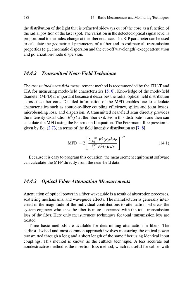
calculate the MFD using the Petermann II equation. The Petermann II expression is
given by Eq. (2.73) in terms of the field intensity distribution as [7, 8]
MFD = 2
2
∞
0 E
2
(r )r
3 dr
∞
0 E 2 (r )rdr
1/2
(14.1)
Because it is easy to program this equation, the measurement equipment software
can calculate the MFP directly from the near-field data.
14.4.3 Optical Fiber Attenuation Measurements
Attenuation of optical power in a fiber waveguide is a result of absorption processes,
scattering mechanisms, and waveguide effects. The manufacturer is generally interested in the magnitude of the individual contributions to attenuation, whereas the
system engineer who uses the fiber is more concerned with the total transmission
loss of the fiber. Here only measurement techniques for total transmission loss are
treated.
Three basic methods are available for determining attenuation in fibers. The
earliest devised and most common approach involves measuring the optical power
transmitted through a long and a short length of the same fiber using identical input
couplings. This method is known as the cutback technique. A less accurate but
nondestructive method is the insertion-loss method, which is useful for cables with