

568
13 Fiber Optic Communication Networks
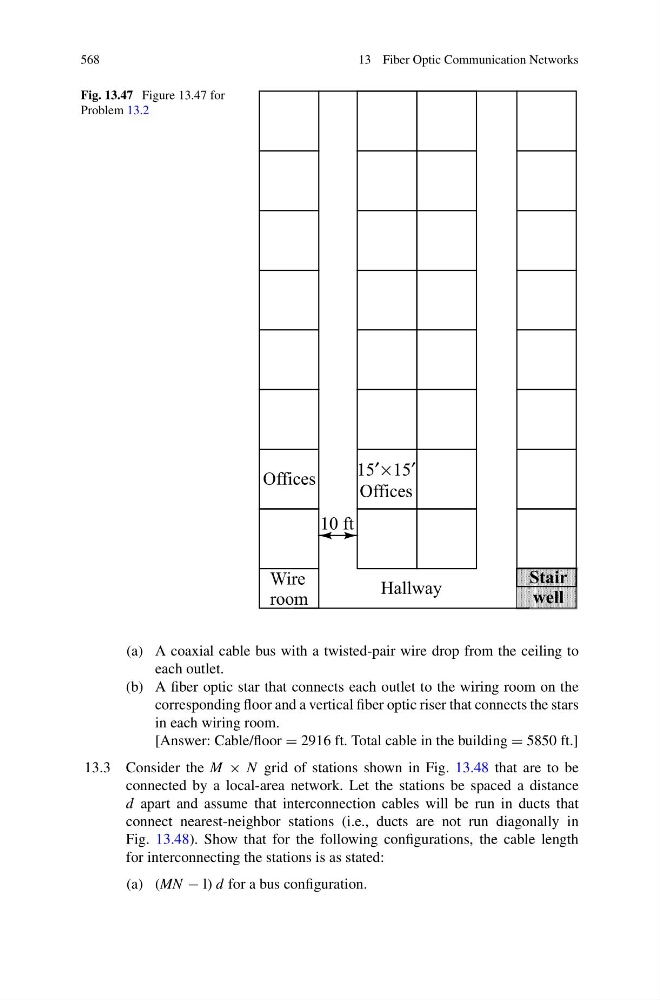
Fig. 13.47 Figure 13.47 for
Problem 13.2
(a) A coaxial cable bus with a twisted-pair wire drop from the ceiling to
each outlet.
(b) A fiber optic star that connects each outlet to the wiring room on the
corresponding floor and a vertical fiber optic riser that connects the stars
in each wiring room.
[Answer: Cable/floor = 2916 ft. Total cable in the building = 5850 ft.]
13.3 Consider the M × N grid of stations shown in Fig. 13.48 that are to be
connected by a local-area network. Let the stations be spaced a distance
d apart and assume that interconnection cables will be run in ducts that
connect nearest-neighbor stations (i.e., ducts are not run diagonally in
Fig. 13.48). Show that for the following configurations, the cable length
for interconnecting the stations is as stated:
(a) (MN − l) d for a bus configuration.