

13.8 Passive Optical Networks
557
13.8.1 Basic Architectures for PONs
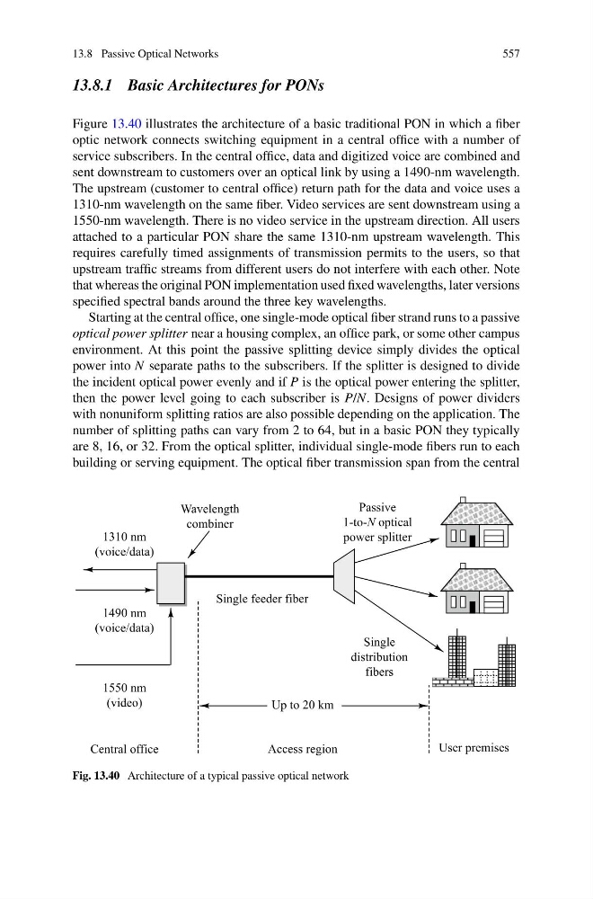
Figure 13.40 illustrates the architecture of a basic traditional PON in which a fiber
optic network connects switching equipment in a central office with a number of
service subscribers. In the central office, data and digitized voice are combined and
sent downstream to customers over an optical link by using a 1490-nm wavelength.
The upstream (customer to central office) return path for the data and voice uses a
1310-nm wavelength on the same fiber. Video services are sent downstream using a
1550-nm wavelength. There is no video service in the upstream direction. All users
attached to a particular PON share the same 1310-nm upstream wavelength. This
requires carefully timed assignments of transmission permits to the users, so that
upstream traffic streams from different users do not interfere with each other. Note
that whereas the original PON implementation used fixed wavelengths, later versions
specified spectral bands around the three key wavelengths.
Starting at the central office, one single-mode optical fiber strand runs to a passive
optical power splitter near a housing complex, an office park, or some other campus
environment. At this point the passive splitting device simply divides the optical
power into N separate paths to the subscribers. If the splitter is designed to divide
the incident optical power evenly and if P is the optical power entering the splitter,
then the power level going to each subscriber is P/N. Designs of power dividers
with nonuniform splitting ratios are also possible depending on the application. The
number of splitting paths can vary from 2 to 64, but in a basic PON they typically
are 8, 16, or 32. From the optical splitter, individual single-mode fibers run to each
building or serving equipment. The optical fiber transmission span from the central
Fig. 13.40 Architecture of a typical passive optical network