

540
13 Fiber Optic Communication Networks
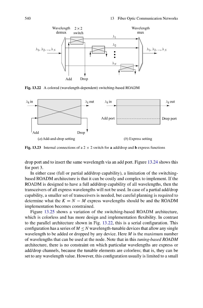
Fig. 13.22 A colored (wavelength-dependent) switching-based ROADM
Fig. 13.23 Internal connections of a 2 × 2 switch for a add/drop and b express functions
drop port and to insert the same wavelength via an add port. Figure 13.24 shows this
for port 3.
In either case (full or partial add/drop capability), a limitation of the switchingbased ROADM architecture is that it can be costly and complex to implement. If the
ROADM is designed to have a full add/drop capability of all wavelengths, then the
transceivers of all express wavelengths will not be used. In case of a partial add/drop
capability, a smaller set of transceivers is needed, but careful planning is required to
determine what the K = N − M express wavelengths should be and the ROADM
implementation becomes constrained.
Figure 13.25 shows a variation of the switching-based ROADM architecture,
which is colorless and has more design and implementation flexibility. In contrast
to the parallel architecture shown in Fig. 13.22, this is a serial configuration. This
configuration has a series of M ≤ N wavelength-tunable devices that allow any single
wavelength to be added or dropped by any device. Here M is the maximum number
of wavelengths that can be used at the node. Note that in this tuning-based ROADM
architecture, there is no constraint on which particular wavelengths are express or
add/drop channels, because the tunable elements are colorless; that is, they can be
set to any wavelength value. However, this configuration usually is limited to a small