

13.5 Schemes for Optical Add/Drop Multiplexing
539
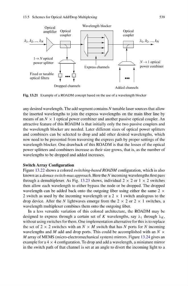
Fig. 13.21 Example of a ROADM concept based on the use of a wavelength blocker
any desired wavelength. The add segment contains N tunable laser sources that allow
the inserted wavelengths to join the express wavelengths on the main fiber line by
means of an N × 1 optical power combiner and another passive optical coupler. An
attractive feature of this ROADM is that initially only the two passive couplers and
the wavelength blocker are needed. Later different sizes of optical power splitters
and combiners can be selected to drop and add other desired wavelengths, which
now need to be prevented from traversing the express path by proper settings of the
wavelength blocker. One drawback of this ROADM is that the losses of the optical
power splitters and combiners increase as their size grows, that is, as the number of
wavelengths to be dropped and added increases.
Switch Array Configuration
Figure 13.22 shows a colored switching-based ROADM configuration, which is also
known as a demux-switch-mux approach. Here the N incoming wavelengths first pass
through a demultiplexer. As Fig. 13.23 shows, individual 2 × 2 or 1 × 2 switches
then allow each wavelength to either bypass the node or be dropped. The dropped
wavelength can be added back onto the outgoing fiber using either the same 2 ×
2 switch as used by the incoming wavelength or a 2 × 1 switch analogous to the
drop device. After the N lightwaves emerge from the 2 × 2 or 2 × 1 switches, a
wavelength multiplexer combines them onto the outgoing fiber.
In a less versatile variation of this colored architecture, the ROADM may be
designed to express through a certain set of K wavelengths, say λ 1 through λ K ,
without using switches for them. One implementation alternative for this is to replace
the set of 2 × 2 switches with an N × M switch that has N ports for N incoming
wavelengths and M add and drop ports. This could be accomplished with an N ×
M array of MEMS (micro-electromechanical system) mirrors. Figure 13.24 gives an
example for a 4 × 4 configuration. To drop and add a wavelength, a miniature mirror
in the switch path of that channel is set at an angle to divert the incoming light to a