

34
2 Optical Fiber Structures and Light Guiding Principles
z
Magnetic
field
Electric field
Direction
of wave
propagation
Wave
vector
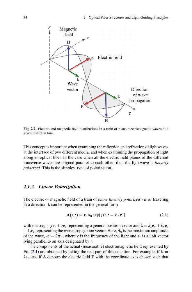
Fig. 2.2 Electric and magnetic field distributions in a train of plane electromagnetic waves at a
given instant in time
This concept is important when examining the reflection and refraction of lightwaves
at the interface of two different media, and when examining the propagation of light
along an optical fiber. In the case when all the electric field planes of the different
transverse waves are aligned parallel to each other, then the lightwave is linearly
polarized. This is the simplest type of polarization.
2.1.2 Linear Polarization
The electric or magnetic field of a train of plane linearly polarized waves traveling
in a direction k can be represented in the general form
A
r , t
= e i A 0 exp[ j (ωt − k · r)]
(2.1)
with r = xe x + ye y + ze z representing a general position vector and k = k x e x + k y e y
+ k z e z representing the wave propagation vector. Here, A 0 is the maximum amplitude
of the wave, ω = 2πν, where v is the frequency of the light and e i is a unit vector
lying parallel to an axis designated by i.
The components of the actual (measurable) electromagnetic field represented by
Eq. (2.1) are obtained by taking the real part of this equation. For example, if k =
ke z , and if A denotes the electric field E with the coordinate axes chosen such that
2 Optical Fiber Structures and Light Guiding Principles
z
Magnetic
field
Electric field
Direction
of wave
propagation
Wave
vector
Fig. 2.2 Electric and magnetic field distributions in a train of plane electromagnetic waves at a
given instant in time
This concept is important when examining the reflection and refraction of lightwaves
at the interface of two different media, and when examining the propagation of light
along an optical fiber. In the case when all the electric field planes of the different
transverse waves are aligned parallel to each other, then the lightwave is linearly
polarized. This is the simplest type of polarization.
2.1.2 Linear Polarization
The electric or magnetic field of a train of plane linearly polarized waves traveling
in a direction k can be represented in the general form
A
r , t
= e i A 0 exp[ j (ωt − k · r)]
(2.1)
with r = xe x + ye y + ze z representing a general position vector and k = k x e x + k y e y
+ k z e z representing the wave propagation vector. Here, A 0 is the maximum amplitude
of the wave, ω = 2πν, where v is the frequency of the light and e i is a unit vector
lying parallel to an axis designated by i.
The components of the actual (measurable) electromagnetic field represented by
Eq. (2.1) are obtained by taking the real part of this equation. For example, if k =
ke z , and if A denotes the electric field E with the coordinate axes chosen such that