

11.6 Fiber Link Applications
461
11.6.2 Use of In-Line Amplifiers
In a long transmission system, optical amplifiers are needed to periodically restore
the power level after it has decreased due to attenuation in the fiber. Normally, the
gain of each EDFA in this amplifier chain is chosen to compensate exactly for the
signal loss incurred in the preceding fiber section of length L, that is, G = exp(+ α L).
The accumulated ASE noise is the dominant degradation factor in such a cascaded
chain of amplifiers.
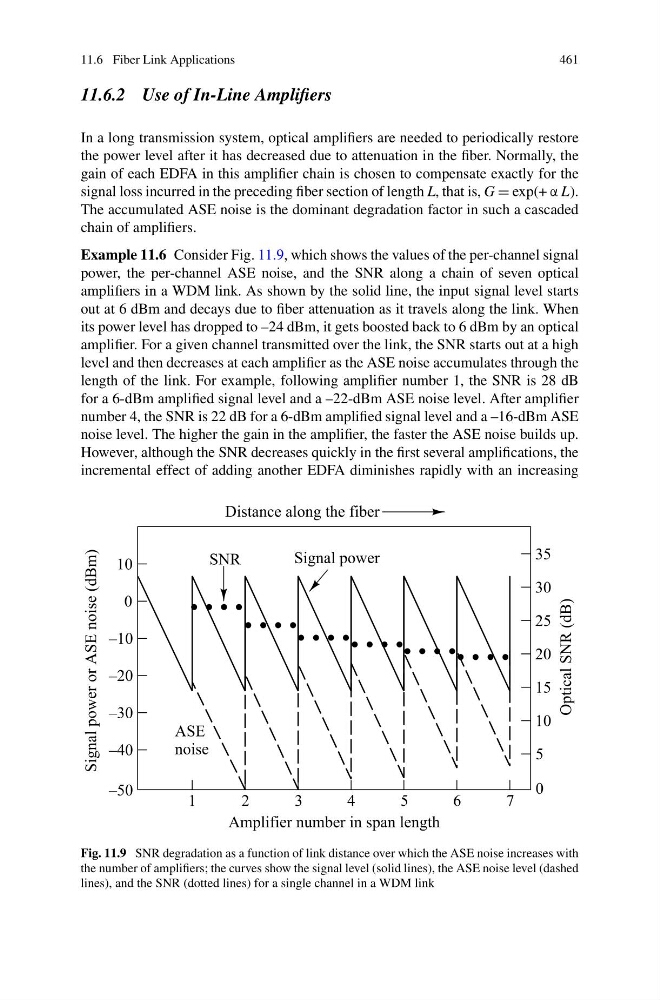
Example 11.6 Consider Fig. 11.9, which shows the values of the per-channel signal
power, the per-channel ASE noise, and the SNR along a chain of seven optical
amplifiers in a WDM link. As shown by the solid line, the input signal level starts
out at 6 dBm and decays due to fiber attenuation as it travels along the link. When
its power level has dropped to –24 dBm, it gets boosted back to 6 dBm by an optical
amplifier. For a given channel transmitted over the link, the SNR starts out at a high
level and then decreases at each amplifier as the ASE noise accumulates through the
length of the link. For example, following amplifier number 1, the SNR is 28 dB
for a 6-dBm amplified signal level and a –22-dBm ASE noise level. After amplifier
number 4, the SNR is 22 dB for a 6-dBm amplified signal level and a –16-dBm ASE
noise level. The higher the gain in the amplifier, the faster the ASE noise builds up.
However, although the SNR decreases quickly in the first several amplifications, the
incremental effect of adding another EDFA diminishes rapidly with an increasing
Fig. 11.9 SNR degradation as a function of link distance over which the ASE noise increases with
the number of amplifiers; the curves show the signal level (solid lines), the ASE noise level (dashed
lines), and the SNR (dotted lines) for a single channel in a WDM link
461
11.6.2 Use of In-Line Amplifiers
In a long transmission system, optical amplifiers are needed to periodically restore
the power level after it has decreased due to attenuation in the fiber. Normally, the
gain of each EDFA in this amplifier chain is chosen to compensate exactly for the
signal loss incurred in the preceding fiber section of length L, that is, G = exp(+ α L).
The accumulated ASE noise is the dominant degradation factor in such a cascaded
chain of amplifiers.
Example 11.6 Consider Fig. 11.9, which shows the values of the per-channel signal
power, the per-channel ASE noise, and the SNR along a chain of seven optical
amplifiers in a WDM link. As shown by the solid line, the input signal level starts
out at 6 dBm and decays due to fiber attenuation as it travels along the link. When
its power level has dropped to –24 dBm, it gets boosted back to 6 dBm by an optical
amplifier. For a given channel transmitted over the link, the SNR starts out at a high
level and then decreases at each amplifier as the ASE noise accumulates through the
length of the link. For example, following amplifier number 1, the SNR is 28 dB
for a 6-dBm amplified signal level and a –22-dBm ASE noise level. After amplifier
number 4, the SNR is 22 dB for a 6-dBm amplified signal level and a –16-dBm ASE
noise level. The higher the gain in the amplifier, the faster the ASE noise builds up.
However, although the SNR decreases quickly in the first several amplifications, the
incremental effect of adding another EDFA diminishes rapidly with an increasing
Fig. 11.9 SNR degradation as a function of link distance over which the ASE noise increases with
the number of amplifiers; the curves show the signal level (solid lines), the ASE noise level (dashed
lines), and the SNR (dotted lines) for a single channel in a WDM link