

454
11 Basics of Optical Amplifiers
where σ e is the signal-emission cross section and ρ is the rare-earth element concentration. When determining the maximum gain, Eqs. (11.19) and (11.21) must be
considered together. Consequently, the maximum possible EDFA gain is given by
the lowest of the two gain expressions:
G ≤ min
exp(ρσ e L), 1 +
λ p
λ s
P p,in
P s,in
(11.22)
Because G = P s,out /P s,in = exp(ρσ e L), it follows similarly that the maximum possible
EDFA output power is given by the minimum of the two expressions:
P s,out ≤ min
P s,in exp(ρσ e L), P s,in +
λ p
λ s
P p,in
(11.23)
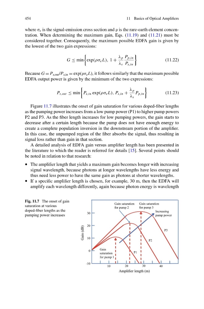
Figure 11.7 illustrates the onset of gain saturation for various doped-fiber lengths
as the pumping power increases from a low pump power (P1) to higher pump powers
P2 and P3. As the fiber length increases for low pumping powers, the gain starts to
decrease after a certain length because the pump does not have enough energy to
create a complete population inversion in the downstream portion of the amplifier.
In this case, the unpumped region of the fiber absorbs the signal, thus resulting in
signal loss rather than gain in that section.
A detailed analysis of EDFA gain versus amplifier length has been presented in
the literature to which the reader is referred for details [15]. Several points should
be noted in relation to that research:
• The amplifier length that yields a maximum gain becomes longer with increasing
signal wavelength, because photons at longer wavelengths have less energy and
thus need less power to have the same gain as photons at shorter wavelengths.
• If a specific amplifier length is chosen, for example, 30 m, then the EDFA will
amplify each wavelength differently, again because photon energy is wavelength
Fig. 11.7 The onset of gain
saturation at various
doped-fiber lengths as the
pumping power increases
Gain (dB)
Amplifier length (m)
30
10
10
20
20
30
40
0
-10
Increasing
pump power
P1
P2
P3
Gain saturation
for pump 2
Gain saturation
for pump 3
Gain
saturation
for pump 1
11 Basics of Optical Amplifiers
where σ e is the signal-emission cross section and ρ is the rare-earth element concentration. When determining the maximum gain, Eqs. (11.19) and (11.21) must be
considered together. Consequently, the maximum possible EDFA gain is given by
the lowest of the two gain expressions:
G ≤ min
exp(ρσ e L), 1 +
λ p
λ s
P p,in
P s,in
(11.22)
Because G = P s,out /P s,in = exp(ρσ e L), it follows similarly that the maximum possible
EDFA output power is given by the minimum of the two expressions:
P s,out ≤ min
P s,in exp(ρσ e L), P s,in +
λ p
λ s
P p,in
(11.23)
Figure 11.7 illustrates the onset of gain saturation for various doped-fiber lengths
as the pumping power increases from a low pump power (P1) to higher pump powers
P2 and P3. As the fiber length increases for low pumping powers, the gain starts to
decrease after a certain length because the pump does not have enough energy to
create a complete population inversion in the downstream portion of the amplifier.
In this case, the unpumped region of the fiber absorbs the signal, thus resulting in
signal loss rather than gain in that section.
A detailed analysis of EDFA gain versus amplifier length has been presented in
the literature to which the reader is referred for details [15]. Several points should
be noted in relation to that research:
• The amplifier length that yields a maximum gain becomes longer with increasing
signal wavelength, because photons at longer wavelengths have less energy and
thus need less power to have the same gain as photons at shorter wavelengths.
• If a specific amplifier length is chosen, for example, 30 m, then the EDFA will
amplify each wavelength differently, again because photon energy is wavelength
Fig. 11.7 The onset of gain
saturation at various
doped-fiber lengths as the
pumping power increases
Gain (dB)
Amplifier length (m)
30
10
10
20
20
30
40
0
-10
Increasing
pump power
P1
P2
P3
Gain saturation
for pump 2
Gain saturation
for pump 3
Gain
saturation
for pump 1