

11.3 Erbium-Doped Fiber Amplifiers
451
incoming signal photon. The widths of the metastable level and the ground-state
level allow high degrees of stimulated emissions to occur in the 1530-to-1560-nm
range.
11.3.2 Construction of an EDFA
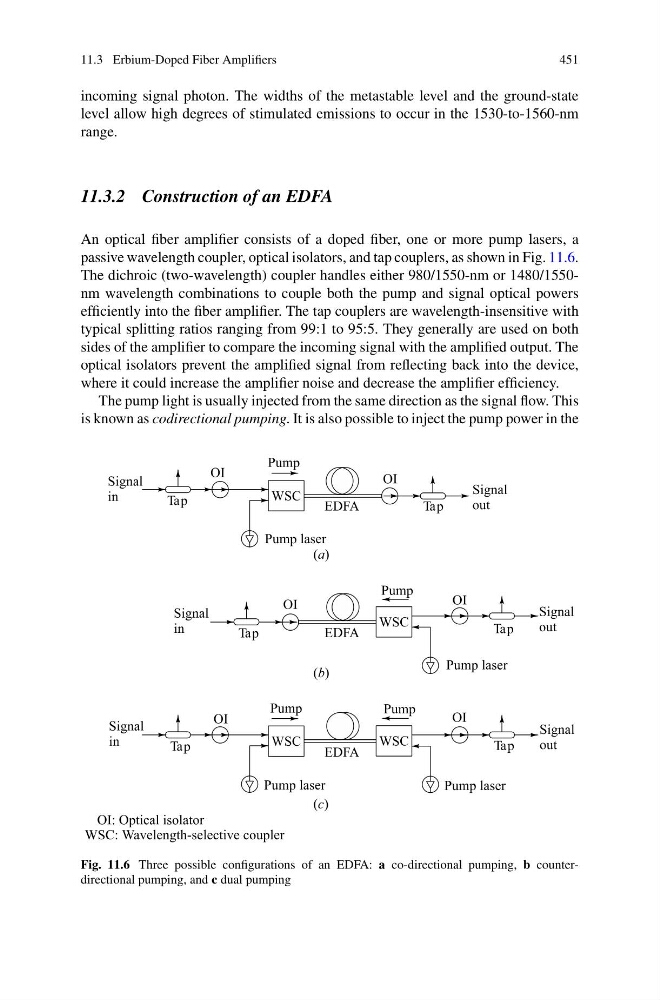
An optical fiber amplifier consists of a doped fiber, one or more pump lasers, a
passive wavelength coupler, optical isolators, and tap couplers, as shown in Fig. 11.6.
The dichroic (two-wavelength) coupler handles either 980/1550-nm or 1480/1550nm wavelength combinations to couple both the pump and signal optical powers
efficiently into the fiber amplifier. The tap couplers are wavelength-insensitive with
typical splitting ratios ranging from 99:1 to 95:5. They generally are used on both
sides of the amplifier to compare the incoming signal with the amplified output. The
optical isolators prevent the amplified signal from reflecting back into the device,
where it could increase the amplifier noise and decrease the amplifier efficiency.
The pump light is usually injected from the same direction as the signal flow. This
is known as codirectional pumping. It is also possible to inject the pump power in the
Fig. 11.6 Three possible configurations of an EDFA: a co-directional pumping, b counterdirectional pumping, and c dual pumping
451
incoming signal photon. The widths of the metastable level and the ground-state
level allow high degrees of stimulated emissions to occur in the 1530-to-1560-nm
range.
11.3.2 Construction of an EDFA
An optical fiber amplifier consists of a doped fiber, one or more pump lasers, a
passive wavelength coupler, optical isolators, and tap couplers, as shown in Fig. 11.6.
The dichroic (two-wavelength) coupler handles either 980/1550-nm or 1480/1550nm wavelength combinations to couple both the pump and signal optical powers
efficiently into the fiber amplifier. The tap couplers are wavelength-insensitive with
typical splitting ratios ranging from 99:1 to 95:5. They generally are used on both
sides of the amplifier to compare the incoming signal with the amplified output. The
optical isolators prevent the amplified signal from reflecting back into the device,
where it could increase the amplifier noise and decrease the amplifier efficiency.
The pump light is usually injected from the same direction as the signal flow. This
is known as codirectional pumping. It is also possible to inject the pump power in the
Fig. 11.6 Three possible configurations of an EDFA: a co-directional pumping, b counterdirectional pumping, and c dual pumping