

442
11 Basics of Optical Amplifiers
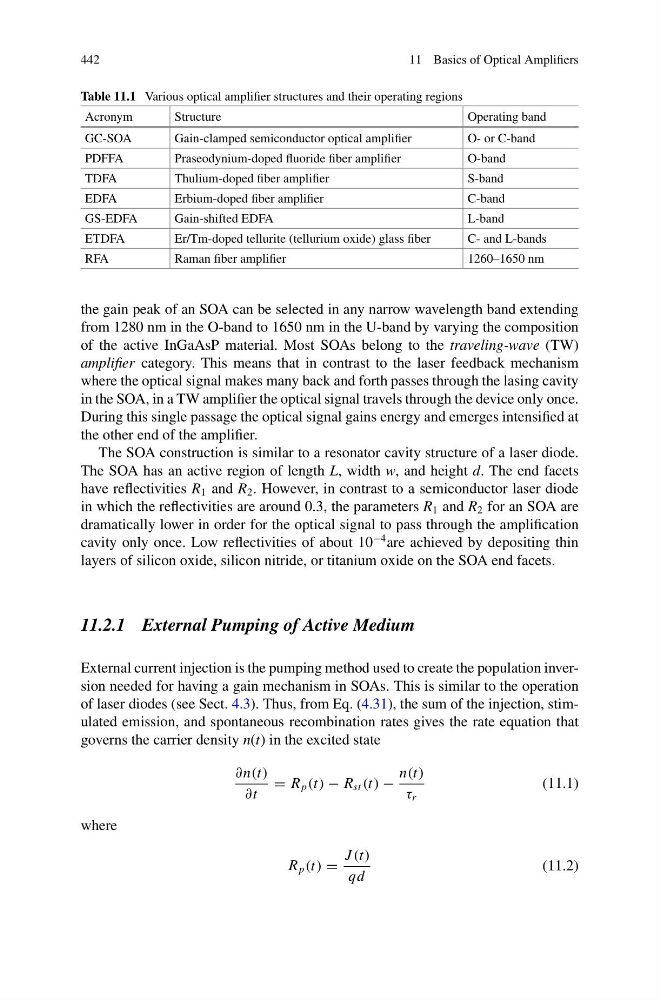
Table 11.1 Various optical amplifier structures and their operating regions
Acronym
Structure
Operating band
GC-SOA
Gain-clamped semiconductor optical amplifier
O- or C-band
PDFFA
Praseodynium-doped fluoride fiber amplifier
O-band
TDFA
Thulium-doped fiber amplifier
S-band
EDFA
Erbium-doped fiber amplifier
C-band
GS-EDFA
Gain-shifted EDFA
L-band
ETDFA
Er/Tm-doped tellurite (tellurium oxide) glass fiber
C- and L-bands
RFA
Raman fiber amplifier
1260–1650 nm
the gain peak of an SOA can be selected in any narrow wavelength band extending
from 1280 nm in the O-band to 1650 nm in the U-band by varying the composition
of the active InGaAsP material. Most SOAs belong to the traveling-wave (TW)
amplifier category. This means that in contrast to the laser feedback mechanism
where the optical signal makes many back and forth passes through the lasing cavity
in the SOA, in a TW amplifier the optical signal travels through the device only once.
During this single passage the optical signal gains energy and emerges intensified at
the other end of the amplifier.
The SOA construction is similar to a resonator cavity structure of a laser diode.
The SOA has an active region of length L, width w, and height d. The end facets
have reflectivities R 1 and R 2 . However, in contrast to a semiconductor laser diode
in which the reflectivities are around 0.3, the parameters R 1 and R 2 for an SOA are
dramatically lower in order for the optical signal to pass through the amplification
cavity only once. Low reflectivities of about 10
−4 are achieved by depositing thin
layers of silicon oxide, silicon nitride, or titanium oxide on the SOA end facets.
11.2.1 External Pumping of Active Medium
External current injection is the pumping method used to create the population inversion needed for having a gain mechanism in SOAs. This is similar to the operation
of laser diodes (see Sect. 4.3). Thus, from Eq. (4.31), the sum of the injection, stimulated emission, and spontaneous recombination rates gives the rate equation that
governs the carrier density n(t) in the excited state
∂n(t)
∂t
= R p (t) − R st (t) −
n(t)
τ r
(11.1)
where
R p (t) =
J (t)
qd
(11.2)
11 Basics of Optical Amplifiers
Table 11.1 Various optical amplifier structures and their operating regions
Acronym
Structure
Operating band
GC-SOA
Gain-clamped semiconductor optical amplifier
O- or C-band
PDFFA
Praseodynium-doped fluoride fiber amplifier
O-band
TDFA
Thulium-doped fiber amplifier
S-band
EDFA
Erbium-doped fiber amplifier
C-band
GS-EDFA
Gain-shifted EDFA
L-band
ETDFA
Er/Tm-doped tellurite (tellurium oxide) glass fiber
C- and L-bands
RFA
Raman fiber amplifier
1260–1650 nm
the gain peak of an SOA can be selected in any narrow wavelength band extending
from 1280 nm in the O-band to 1650 nm in the U-band by varying the composition
of the active InGaAsP material. Most SOAs belong to the traveling-wave (TW)
amplifier category. This means that in contrast to the laser feedback mechanism
where the optical signal makes many back and forth passes through the lasing cavity
in the SOA, in a TW amplifier the optical signal travels through the device only once.
During this single passage the optical signal gains energy and emerges intensified at
the other end of the amplifier.
The SOA construction is similar to a resonator cavity structure of a laser diode.
The SOA has an active region of length L, width w, and height d. The end facets
have reflectivities R 1 and R 2 . However, in contrast to a semiconductor laser diode
in which the reflectivities are around 0.3, the parameters R 1 and R 2 for an SOA are
dramatically lower in order for the optical signal to pass through the amplification
cavity only once. Low reflectivities of about 10
−4 are achieved by depositing thin
layers of silicon oxide, silicon nitride, or titanium oxide on the SOA end facets.
11.2.1 External Pumping of Active Medium
External current injection is the pumping method used to create the population inversion needed for having a gain mechanism in SOAs. This is similar to the operation
of laser diodes (see Sect. 4.3). Thus, from Eq. (4.31), the sum of the injection, stimulated emission, and spontaneous recombination rates gives the rate equation that
governs the carrier density n(t) in the excited state
∂n(t)
∂t
= R p (t) − R st (t) −
n(t)
τ r
(11.1)
where
R p (t) =
J (t)
qd
(11.2)