

426
10 Wavelength Division Multiplexing (WDM)
λ =
x
L f
n s d
m
n c
n g
=
x
L f
λ c d
L
n s
n g
(10.64)
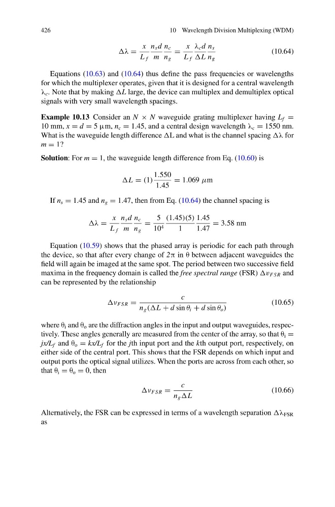
Equations (10.63) and (10.64) thus define the pass frequencies or wavelengths
for which the multiplexer operates, given that it is designed for a central wavelength
λ c . Note that by making L large, the device can multiplex and demultiplex optical
signals with very small wavelength spacings.
Example 10.13 Consider an N × N waveguide grating multiplexer having L f =
10 mm, x = d = 5 μm, n c = 1.45, and a central design wavelength λ c = 1550 nm.
What is the waveguide length difference L and what is the channel spacing λ for
m = 1?
Solution: For m = 1, the waveguide length difference from Eq. (10.60) is
L = (1)
1.550
1.45
= 1.069 μm
If n s = 1.45 and n g = 1.47, then from Eq. (10.64) the channel spacing is
λ =
x
L f
n s d
m
n c
n g
=
5
10 4
(1.45)(5)
1
1.45
1.47
= 3.58 nm
Equation (10.59) shows that the phased array is periodic for each path through
the device, so that after every change of 2π in θ between adjacent waveguides the
field will again be imaged at the same spot. The period between two successive field
maxima in the frequency domain is called the free spectral range (FSR) v F S R and
can be represented by the relationship
ν F S R =
c
n g (L + d sin θ i + d sin θ o )
(10.65)
where θ i and θ o are the diffraction angles in the input and output waveguides, respectively. These angles generally are measured from the center of the array, so that θ i =
jx/L f and θ o = kx/L f for the jth input port and the kth output port, respectively, on
either side of the central port. This shows that the FSR depends on which input and
output ports the optical signal utilizes. When the ports are across from each other, so
that θ i = θ o = 0, then
ν F S R =
c
n g L
(10.66)
Alternatively, the FSR can be expressed in terms of a wavelength separation λ FSR
as
10 Wavelength Division Multiplexing (WDM)
λ =
x
L f
n s d
m
n c
n g
=
x
L f
λ c d
L
n s
n g
(10.64)
Equations (10.63) and (10.64) thus define the pass frequencies or wavelengths
for which the multiplexer operates, given that it is designed for a central wavelength
λ c . Note that by making L large, the device can multiplex and demultiplex optical
signals with very small wavelength spacings.
Example 10.13 Consider an N × N waveguide grating multiplexer having L f =
10 mm, x = d = 5 μm, n c = 1.45, and a central design wavelength λ c = 1550 nm.
What is the waveguide length difference L and what is the channel spacing λ for
m = 1?
Solution: For m = 1, the waveguide length difference from Eq. (10.60) is
L = (1)
1.550
1.45
= 1.069 μm
If n s = 1.45 and n g = 1.47, then from Eq. (10.64) the channel spacing is
λ =
x
L f
n s d
m
n c
n g
=
5
10 4
(1.45)(5)
1
1.45
1.47
= 3.58 nm
Equation (10.59) shows that the phased array is periodic for each path through
the device, so that after every change of 2π in θ between adjacent waveguides the
field will again be imaged at the same spot. The period between two successive field
maxima in the frequency domain is called the free spectral range (FSR) v F S R and
can be represented by the relationship
ν F S R =
c
n g (L + d sin θ i + d sin θ o )
(10.65)
where θ i and θ o are the diffraction angles in the input and output waveguides, respectively. These angles generally are measured from the center of the array, so that θ i =
jx/L f and θ o = kx/L f for the jth input port and the kth output port, respectively, on
either side of the central port. This shows that the FSR depends on which input and
output ports the optical signal utilizes. When the ports are across from each other, so
that θ i = θ o = 0, then
ν F S R =
c
n g L
(10.66)
Alternatively, the FSR can be expressed in terms of a wavelength separation λ FSR
as