

408
10 Wavelength Division Multiplexing (WDM)
Hence, the length difference in the interferometer arms should be
L =
2n e f f
1
λ 1
−
1
λ 2
−1
=
c
2n e f f ν
(10.41)
where ν is the frequency separation of the two wavelengths.
Example 10.11
(a) Assume that the input wavelengths of a 2 × 2 silicon MZI are separated by
10 GHz (i.e., λ = 0.08 nm at 1550 nm). With n eff = 1.5 in a silicon waveguide,
it can be seen from (Eq. 10.41) that the waveguide length difference must be.
L =
3 × 10
8 m/s
2(1.5)10 10 /s
= 10 mm
(b) If the frequency separation is 130 GHz (i.e., λ = 1 nm), then L = 0.77 mm.
Using basic 2 × 2 MZIs, any size N × N multiplexer (with N = 2
n ) can be
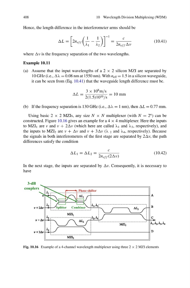
constructed. Figure 10.16 gives an example for a 4 × 4 multiplexer. Here the inputs
to MZI 1 are v and v + 2v (which here are called λ 1 and λ 3 , respectively), and
the inputs to MZI 2 are v + v and v + 3v (λ 2 and λ 4 , respectively). Because
the signals in both interferometers of the first stage are separated by 2v, the path
differences satisfy the condition
L 1 = L 2 =
c
2n e f f (2ν)
(10.42)
In the next stage, the inputs are separated by v. Consequently, it is necessary to
have
3-dB
couplers
Splitter Combiner
Phase shifter
Fig. 10.16 Example of a 4-channel wavelength multiplexer using three 2 × 2 MZI elements
10 Wavelength Division Multiplexing (WDM)
Hence, the length difference in the interferometer arms should be
L =
2n e f f
1
λ 1
−
1
λ 2
−1
=
c
2n e f f ν
(10.41)
where ν is the frequency separation of the two wavelengths.
Example 10.11
(a) Assume that the input wavelengths of a 2 × 2 silicon MZI are separated by
10 GHz (i.e., λ = 0.08 nm at 1550 nm). With n eff = 1.5 in a silicon waveguide,
it can be seen from (Eq. 10.41) that the waveguide length difference must be.
L =
3 × 10
8 m/s
2(1.5)10 10 /s
= 10 mm
(b) If the frequency separation is 130 GHz (i.e., λ = 1 nm), then L = 0.77 mm.
Using basic 2 × 2 MZIs, any size N × N multiplexer (with N = 2
n ) can be
constructed. Figure 10.16 gives an example for a 4 × 4 multiplexer. Here the inputs
to MZI 1 are v and v + 2v (which here are called λ 1 and λ 3 , respectively), and
the inputs to MZI 2 are v + v and v + 3v (λ 2 and λ 4 , respectively). Because
the signals in both interferometers of the first stage are separated by 2v, the path
differences satisfy the condition
L 1 = L 2 =
c
2n e f f (2ν)
(10.42)
In the next stage, the inputs are separated by v. Consequently, it is necessary to
have
3-dB
couplers
Splitter Combiner
Phase shifter
Fig. 10.16 Example of a 4-channel wavelength multiplexer using three 2 × 2 MZI elements