

10.1 Concepts of WDM
385
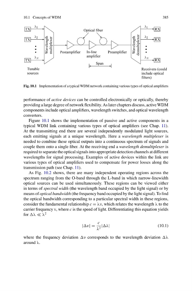
Fig. 10.1 Implementation of a typical WDM network containing various types of optical amplifiers
performance of active devices can be controlled electronically or optically, thereby
providing a large degree of network flexibility. As later chapters discuss, active WDM
components include optical amplifiers, wavelength switches, and optical wavelength
converters.
Figure 10.1 shows the implementation of passive and active components in a
typical WDM link containing various types of optical amplifiers (see Chap. 11).
At the transmitting end there are several independently modulated light sources,
each emitting signals at a unique wavelength. Here a wavelength multiplexer is
needed to combine these optical outputs into a continuous spectrum of signals and
couple them onto a single fiber. At the receiving end a wavelength demultiplexer is
required to separate the optical signals into appropriate detection channels at different
wavelengths for signal processing. Examples of active devices within the link are
various types of optical amplifiers used to compensate for power losses along the
transmission path (see Chap. 11).
As Fig. 10.2 shows, there are many independent operating regions across the
spectrum ranging from the O-band through the L-band in which narrow-linewidth
optical sources can be used simultaneously. These regions can be viewed either
in terms of spectral width (the wavelength band occupied by the light signal) or by
means of optical bandwidth (the frequency band occupied by the light signal). To find
the optical bandwidth corresponding to a particular spectral width in these regions,
consider the fundamental relationship c = λν, which relates the wavelength λ to the
carrier frequency ν, where c is the speed of light. Differentiating this equation yields
for λ
2
|v| =
c
λ 2 |
(10.1)
where the frequency deviation corresponds to the wavelength deviation
around λ.
385
Fig. 10.1 Implementation of a typical WDM network containing various types of optical amplifiers
performance of active devices can be controlled electronically or optically, thereby
providing a large degree of network flexibility. As later chapters discuss, active WDM
components include optical amplifiers, wavelength switches, and optical wavelength
converters.
Figure 10.1 shows the implementation of passive and active components in a
typical WDM link containing various types of optical amplifiers (see Chap. 11).
At the transmitting end there are several independently modulated light sources,
each emitting signals at a unique wavelength. Here a wavelength multiplexer is
needed to combine these optical outputs into a continuous spectrum of signals and
couple them onto a single fiber. At the receiving end a wavelength demultiplexer is
required to separate the optical signals into appropriate detection channels at different
wavelengths for signal processing. Examples of active devices within the link are
various types of optical amplifiers used to compensate for power losses along the
transmission path (see Chap. 11).
As Fig. 10.2 shows, there are many independent operating regions across the
spectrum ranging from the O-band through the L-band in which narrow-linewidth
optical sources can be used simultaneously. These regions can be viewed either
in terms of spectral width (the wavelength band occupied by the light signal) or by
means of optical bandwidth (the frequency band occupied by the light signal). To find
the optical bandwidth corresponding to a particular spectral width in these regions,
consider the fundamental relationship c = λν, which relates the wavelength λ to the
carrier frequency ν, where c is the speed of light. Differentiating this equation yields
for λ
2
|v| =
c
λ 2 |
(10.1)
where the frequency deviation corresponds to the wavelength deviation
around λ.