

364
9 Analog Optical Fiber Channels
As a result of the increasing use of broadband wireless communication devices,
schemes have been investigated and implemented for using analog optical fiber
links for distributing broadband microwave-frequency signals in a variety of applications. The methods for transmitting microwave analog signals in the 0.3–300-GHz
range over an optical fiber link have become known as RF-over-fiber techniques.
Section 9.4 examines the basics of these techniques. Section 9.5 gives an example
of radio-over-fiber links used for in-building distributed antenna systems to provide
wireless LAN and mobile telephony services over a single fiber.
To enable the efficient application of RF-over-fiber techniques, the field of
microwave photonics came into existence. Research in this field encompasses the
study and applications of photonic devices operating at microwave frequencies. In
addition to device developments, microwave photonics also addresses optical signal
processing at microwave speeds and the design and implementation of RF photonic
transmission systems. Section 9.6 gives a brief overview of microwave-photonic
components and their uses.
9.1 Basic Elements of Analog Links
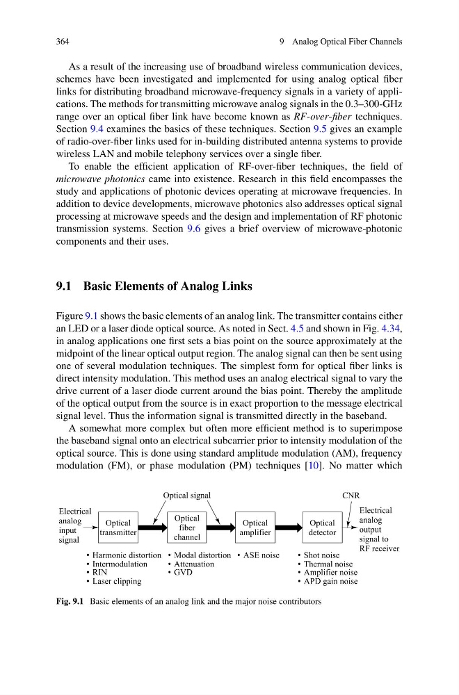
Figure 9.1 shows the basic elements of an analog link. The transmitter contains either
an LED or a laser diode optical source. As noted in Sect. 4.5 and shown in Fig. 4.34,
in analog applications one first sets a bias point on the source approximately at the
midpoint of the linear optical output region. The analog signal can then be sent using
one of several modulation techniques. The simplest form for optical fiber links is
direct intensity modulation. This method uses an analog electrical signal to vary the
drive current of a laser diode current around the bias point. Thereby the amplitude
of the optical output from the source is in exact proportion to the message electrical
signal level. Thus the information signal is transmitted directly in the baseband.
A somewhat more complex but often more efficient method is to superimpose
the baseband signal onto an electrical subcarrier prior to intensity modulation of the
optical source. This is done using standard amplitude modulation (AM), frequency
modulation (FM), or phase modulation (PM) techniques [10]. No matter which
Fig. 9.1 Basic elements of an analog link and the major noise contributors
9 Analog Optical Fiber Channels
As a result of the increasing use of broadband wireless communication devices,
schemes have been investigated and implemented for using analog optical fiber
links for distributing broadband microwave-frequency signals in a variety of applications. The methods for transmitting microwave analog signals in the 0.3–300-GHz
range over an optical fiber link have become known as RF-over-fiber techniques.
Section 9.4 examines the basics of these techniques. Section 9.5 gives an example
of radio-over-fiber links used for in-building distributed antenna systems to provide
wireless LAN and mobile telephony services over a single fiber.
To enable the efficient application of RF-over-fiber techniques, the field of
microwave photonics came into existence. Research in this field encompasses the
study and applications of photonic devices operating at microwave frequencies. In
addition to device developments, microwave photonics also addresses optical signal
processing at microwave speeds and the design and implementation of RF photonic
transmission systems. Section 9.6 gives a brief overview of microwave-photonic
components and their uses.
9.1 Basic Elements of Analog Links
Figure 9.1 shows the basic elements of an analog link. The transmitter contains either
an LED or a laser diode optical source. As noted in Sect. 4.5 and shown in Fig. 4.34,
in analog applications one first sets a bias point on the source approximately at the
midpoint of the linear optical output region. The analog signal can then be sent using
one of several modulation techniques. The simplest form for optical fiber links is
direct intensity modulation. This method uses an analog electrical signal to vary the
drive current of a laser diode current around the bias point. Thereby the amplitude
of the optical output from the source is in exact proportion to the message electrical
signal level. Thus the information signal is transmitted directly in the baseband.
A somewhat more complex but often more efficient method is to superimpose
the baseband signal onto an electrical subcarrier prior to intensity modulation of the
optical source. This is done using standard amplitude modulation (AM), frequency
modulation (FM), or phase modulation (PM) techniques [10]. No matter which
Fig. 9.1 Basic elements of an analog link and the major noise contributors