

8.5 Higher-Order Signal Modulation Formats
353
the form of a pulse in an RZ-DPSK format. Binary data is encoded as either an
optical phase shift of 0 or π between adjacent slots. For example, the information bit
1 may be transmitted by a 180° carrier phase shift relative to the carrier phase in the
previous slot, whereas the information bit 0 is transmitted by no phase shift relative
to the carrier phase in the previous signaling interval. There are many other varieties
of PSK, such as DQPSK described in Sect. 8.5.3.
8.5.3 Differential Quadrature Phase-Shift Keying
Until about 2002, traffic was transmitted over most optical communication systems
at data rates up to 2.5 Gb/s per wavelength using OOK signals in either NRZ or
RZ formats. As the desire grew to transmit data at higher speeds, such as 10 and
40 Gb/s, the idea of using a multilevel modulation format received much attention. Of
particular interest for high-speed transmission is the use of the differential quadrature
phase-shift keying (DQPSK) method. In a multilevel modulation format, more than
one bit per symbol is transmitted. In the DQPSK method, information is encoded by
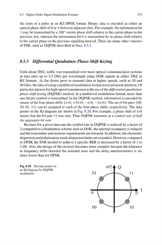
means of the four phase shifts {π /4, +3π /4, −π /4, −3π /4}. The set of bit pairs {00,
10, 01, 11} can be assigned to each of the four phase shifts, respectively. The data
points on the IQ diagram are shown in Fig. 8.20. For example, a phase shift of π /4
means that the bit pair 11 was sent. Thus DQPSK transmits at a symbol rate of half
the aggregate bit rate.
Because for a given data rate the symbol rate in DQPSK is reduced by a factor of
2 compared to a modulation scheme such as OOK, the spectral occupancy is reduced
and the transmitter and receiver requirements are lowered. In addition, the chromatic
dispersion and polarization-mode dispersion limits are extended. However, compared
to DPSK the SNR needed to achieve a specific BER is increased by a factor of 1 to
2 dB. Also, the design of the receiver becomes more complex because the tolerance
to frequency drifts between the transmit laser and the delay interferometers is six
times lower than for DPSK.
Fig. 8.20 The data points on
an IQ diagram for DQPSK
modulation
353
the form of a pulse in an RZ-DPSK format. Binary data is encoded as either an
optical phase shift of 0 or π between adjacent slots. For example, the information bit
1 may be transmitted by a 180° carrier phase shift relative to the carrier phase in the
previous slot, whereas the information bit 0 is transmitted by no phase shift relative
to the carrier phase in the previous signaling interval. There are many other varieties
of PSK, such as DQPSK described in Sect. 8.5.3.
8.5.3 Differential Quadrature Phase-Shift Keying
Until about 2002, traffic was transmitted over most optical communication systems
at data rates up to 2.5 Gb/s per wavelength using OOK signals in either NRZ or
RZ formats. As the desire grew to transmit data at higher speeds, such as 10 and
40 Gb/s, the idea of using a multilevel modulation format received much attention. Of
particular interest for high-speed transmission is the use of the differential quadrature
phase-shift keying (DQPSK) method. In a multilevel modulation format, more than
one bit per symbol is transmitted. In the DQPSK method, information is encoded by
means of the four phase shifts {π /4, +3π /4, −π /4, −3π /4}. The set of bit pairs {00,
10, 01, 11} can be assigned to each of the four phase shifts, respectively. The data
points on the IQ diagram are shown in Fig. 8.20. For example, a phase shift of π /4
means that the bit pair 11 was sent. Thus DQPSK transmits at a symbol rate of half
the aggregate bit rate.
Because for a given data rate the symbol rate in DQPSK is reduced by a factor of
2 compared to a modulation scheme such as OOK, the spectral occupancy is reduced
and the transmitter and receiver requirements are lowered. In addition, the chromatic
dispersion and polarization-mode dispersion limits are extended. However, compared
to DPSK the SNR needed to achieve a specific BER is increased by a factor of 1 to
2 dB. Also, the design of the receiver becomes more complex because the tolerance
to frequency drifts between the transmit laser and the delay interferometers is six
times lower than for DPSK.
Fig. 8.20 The data points on
an IQ diagram for DQPSK
modulation