

348
8 Digital Optical Fiber Links
BER =
e
−ηN p
πηN p
1/2
(8.59)
for ηN p ≥ 5 in OOK homodyne detection.
Drill Problem 8.8 (a) Verify that 10 photons per bit are required to get a
bit-error rate of 10
−9 for an ideal direct-detection OOK system.
(b) Show that for an ideal OOK homodyne system, one needs 36 photons
per pulse to achieve a 10
−9 BER.
PSK Homodyne System
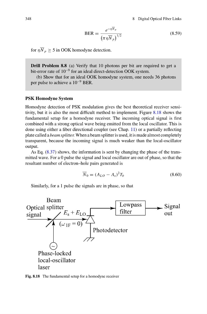
Homodyne detection of PSK modulation gives the best theoretical receiver sensitivity, but it is also the most difficult method to implement. Figure 8.18 shows the
fundamental setup for a homodyne receiver. The incoming optical signal is first
combined with a strong optical wave being emitted from the local oscillator. This is
done using either a fiber directional coupler (see Chap. 11) or a partially reflecting
plate called a beam splitter. When a beam splitter is used, it is made almost completely
transparent, because the incoming signal is much weaker than the local-oscillator
output.
As Eq. (8.37) shows, the information is sent by changing the phase of the transmitted wave. For a 0 pulse the signal and local oscillator are out of phase, so that the
resultant number of electron–hole pairs generated is
N 0 = (A L O − A s )
2 T b
(8.60)
Similarly, for a 1 pulse the signals are in phase, so that
Fig. 8.18 The fundamental setup for a homodyne receiver
8 Digital Optical Fiber Links
BER =
e
−ηN p
πηN p
1/2
(8.59)
for ηN p ≥ 5 in OOK homodyne detection.
Drill Problem 8.8 (a) Verify that 10 photons per bit are required to get a
bit-error rate of 10
−9 for an ideal direct-detection OOK system.
(b) Show that for an ideal OOK homodyne system, one needs 36 photons
per pulse to achieve a 10
−9 BER.
PSK Homodyne System
Homodyne detection of PSK modulation gives the best theoretical receiver sensitivity, but it is also the most difficult method to implement. Figure 8.18 shows the
fundamental setup for a homodyne receiver. The incoming optical signal is first
combined with a strong optical wave being emitted from the local oscillator. This is
done using either a fiber directional coupler (see Chap. 11) or a partially reflecting
plate called a beam splitter. When a beam splitter is used, it is made almost completely
transparent, because the incoming signal is much weaker than the local-oscillator
output.
As Eq. (8.37) shows, the information is sent by changing the phase of the transmitted wave. For a 0 pulse the signal and local oscillator are out of phase, so that the
resultant number of electron–hole pairs generated is
N 0 = (A L O − A s )
2 T b
(8.60)
Similarly, for a 1 pulse the signals are in phase, so that
Fig. 8.18 The fundamental setup for a homodyne receiver