

8.1 Basic Optical Fiber Links
313
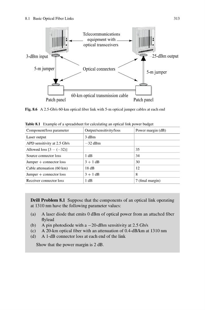
Telecommunications
equipment with
optical transceivers
Fig. 8.6 A 2.5-Gb/s 60-km optical fiber link with 5-m optical jumper cables at each end
Table 8.1 Example of a spreadsheet for calculating an optical link power budget
Component/loss parameter
Output/sensitivity/loss
Power margin (dB)
Laser output
3 dBm
APD sensitivity at 2.5 Gb/s
−32 dBm
Allowed loss [3 − (−32)]
35
Source connector loss
1 dB
34
Jumper + connector loss
3 + 1 dB
30
Cable attenuation (60 km)
18 dB
12
Jumper + connector loss
3 + 1 dB
8
Receiver connector loss
1 dB
7 (final margin)
Drill Problem 8.1 Suppose that the components of an optical link operating
at 1310 nm have the following parameter values:
(a) A laser diode that emits 0 dBm of optical power from an attached fiber
flylead
(b) A pin photodiode with a −20-dBm sensitivity at 2.5 Gb/s
(c) A 20-km optical fiber with an attenuation of 0.4-dB/km at 1310 nm
(d) A 1-dB connector loss at each end of the link
Show that the power margin is 2 dB.
313
Telecommunications
equipment with
optical transceivers
Fig. 8.6 A 2.5-Gb/s 60-km optical fiber link with 5-m optical jumper cables at each end
Table 8.1 Example of a spreadsheet for calculating an optical link power budget
Component/loss parameter
Output/sensitivity/loss
Power margin (dB)
Laser output
3 dBm
APD sensitivity at 2.5 Gb/s
−32 dBm
Allowed loss [3 − (−32)]
35
Source connector loss
1 dB
34
Jumper + connector loss
3 + 1 dB
30
Cable attenuation (60 km)
18 dB
12
Jumper + connector loss
3 + 1 dB
8
Receiver connector loss
1 dB
7 (final margin)
Drill Problem 8.1 Suppose that the components of an optical link operating
at 1310 nm have the following parameter values:
(a) A laser diode that emits 0 dBm of optical power from an attached fiber
flylead
(b) A pin photodiode with a −20-dBm sensitivity at 2.5 Gb/s
(c) A 20-km optical fiber with an attenuation of 0.4-dB/km at 1310 nm
(d) A 1-dB connector loss at each end of the link
Show that the power margin is 2 dB.