

7.4 Burst-Mode Receivers
293
range up to 20 km. In one case, suppose the closest and farthest customers attached
to a common optical power splitter are 20 km apart and that the fiber attenuation is
0.5 dB/km. Then there is a 10-dB difference in the signal amplitudes that arrive at
the OLT from these two users if both have the same upstream laser output level. If
there is an additional optical component in the transmission path going to one of the
customer sites, then the difference in signal levels arriving at the OLT could vary up
to 20 dB.
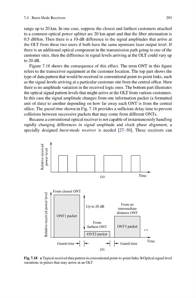
Figure 7.18 shows the consequence of this effect. The term ONT in this figure
refers to the transceiver equipment at the customer location. The top part shows the
type of data pattern that would be received in conventional point-to-point links, such
as the signal levels arriving at a particular customer site from the central office. Here
there is no amplitude variation in the received logic ones. The bottom part illustrates
the optical signal pattern levels that might arrive at the OLT from various customers.
In this case the signal amplitude changes from one information packet (a formatted
unit of data) to another depending on how far away each ONT is from the central
office. The guard time shown in Fig. 7.18 provides a sufficient delay time to prevent
collisions between successive packets that may come from different ONTs.
Because a conventional optical receiver is not capable of instantaneously handling
rapidly changing differences in signal amplitude and clock phase alignment, a
specially designed burst-mode receiver is needed [27–30]. These receivers can
Fig. 7.18 a Typical received data pattern in conventional point-to-point links; b Optical signal level
variations in pulses that may arrive at an OLT
293
range up to 20 km. In one case, suppose the closest and farthest customers attached
to a common optical power splitter are 20 km apart and that the fiber attenuation is
0.5 dB/km. Then there is a 10-dB difference in the signal amplitudes that arrive at
the OLT from these two users if both have the same upstream laser output level. If
there is an additional optical component in the transmission path going to one of the
customer sites, then the difference in signal levels arriving at the OLT could vary up
to 20 dB.
Figure 7.18 shows the consequence of this effect. The term ONT in this figure
refers to the transceiver equipment at the customer location. The top part shows the
type of data pattern that would be received in conventional point-to-point links, such
as the signal levels arriving at a particular customer site from the central office. Here
there is no amplitude variation in the received logic ones. The bottom part illustrates
the optical signal pattern levels that might arrive at the OLT from various customers.
In this case the signal amplitude changes from one information packet (a formatted
unit of data) to another depending on how far away each ONT is from the central
office. The guard time shown in Fig. 7.18 provides a sufficient delay time to prevent
collisions between successive packets that may come from different ONTs.
Because a conventional optical receiver is not capable of instantaneously handling
rapidly changing differences in signal amplitude and clock phase alignment, a
specially designed burst-mode receiver is needed [27–30]. These receivers can
Fig. 7.18 a Typical received data pattern in conventional point-to-point links; b Optical signal level
variations in pulses that may arrive at an OLT