

292
7 Optical Receiver Operation
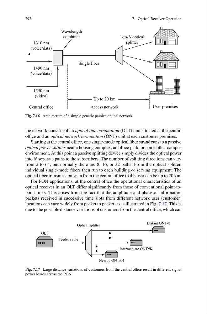
Fig. 7.16 Architecture of a simple generic passive optical network
the network consists of an optical line termination (OLT) unit situated at the central
office and an optical network termination (ONT) unit at each customer premises.
Starting at the central office, one single-mode optical fiber strand runs to a passive
optical power splitter near a housing complex, an office park, or some other campus
environment. At this point a passive splitting device simply divides the optical power
into N separate paths to the subscribers. The number of splitting directions can vary
from 2 to 64, but normally there are 8, 16, or 32 paths. From the optical splitter,
individual single-mode fibers then run to each building or serving equipment. The
optical fiber transmission span from the central office to the user can be up to 20 km.
For PON applications, at the central office the operational characteristics of an
optical receiver in an OLT differ significantly from those of conventional point-topoint links. This arises from the fact that the amplitude and phase of information
packets received in successive time slots from different network user (customer)
locations can vary widely from packet to packet, as is illustrated in Fig. 7.17. This is
due to the possible distance variations of customers from the central office, which can
Fig. 7.17 Large distance variations of customers from the central office result in different signal
power losses across the PON
7 Optical Receiver Operation
Fig. 7.16 Architecture of a simple generic passive optical network
the network consists of an optical line termination (OLT) unit situated at the central
office and an optical network termination (ONT) unit at each customer premises.
Starting at the central office, one single-mode optical fiber strand runs to a passive
optical power splitter near a housing complex, an office park, or some other campus
environment. At this point a passive splitting device simply divides the optical power
into N separate paths to the subscribers. The number of splitting directions can vary
from 2 to 64, but normally there are 8, 16, or 32 paths. From the optical splitter,
individual single-mode fibers then run to each building or serving equipment. The
optical fiber transmission span from the central office to the user can be up to 20 km.
For PON applications, at the central office the operational characteristics of an
optical receiver in an OLT differ significantly from those of conventional point-topoint links. This arises from the fact that the amplitude and phase of information
packets received in successive time slots from different network user (customer)
locations can vary widely from packet to packet, as is illustrated in Fig. 7.17. This is
due to the possible distance variations of customers from the central office, which can
Fig. 7.17 Large distance variations of customers from the central office result in different signal
power losses across the PON