

236
5 Optical Power Coupling
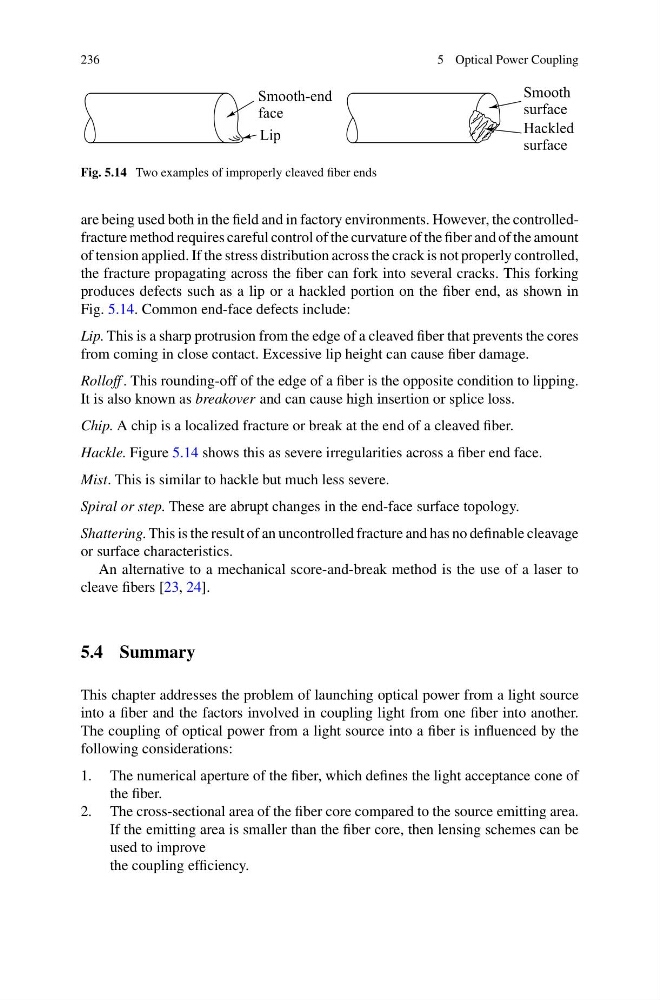
Fig. 5.14 Two examples of improperly cleaved fiber ends
are being used both in the field and in factory environments. However, the controlledfracture method requires careful control of the curvature of the fiber and of the amount
of tension applied. If the stress distribution across the crack is not properly controlled,
the fracture propagating across the fiber can fork into several cracks. This forking
produces defects such as a lip or a hackled portion on the fiber end, as shown in
Fig. 5.14. Common end-face defects include:
Lip. This is a sharp protrusion from the edge of a cleaved fiber that prevents the cores
from coming in close contact. Excessive lip height can cause fiber damage.
Rolloff . This rounding-off of the edge of a fiber is the opposite condition to lipping.
It is also known as breakover and can cause high insertion or splice loss.
Chip. A chip is a localized fracture or break at the end of a cleaved fiber.
Hackle. Figure 5.14 shows this as severe irregularities across a fiber end face.
Mist. This is similar to hackle but much less severe.
Spiral or step. These are abrupt changes in the end-face surface topology.
Shattering. This is the result of an uncontrolled fracture and has no definable cleavage
or surface characteristics.
An alternative to a mechanical score-and-break method is the use of a laser to
cleave fibers [23, 24].
5.4 Summary
This chapter addresses the problem of launching optical power from a light source
into a fiber and the factors involved in coupling light from one fiber into another.
The coupling of optical power from a light source into a fiber is influenced by the
following considerations:
1. The numerical aperture of the fiber, which defines the light acceptance cone of
the fiber.
2. The cross-sectional area of the fiber core compared to the source emitting area.
If the emitting area is smaller than the fiber core, then lensing schemes can be
used to improve
the coupling efficiency.
5 Optical Power Coupling
Fig. 5.14 Two examples of improperly cleaved fiber ends
are being used both in the field and in factory environments. However, the controlledfracture method requires careful control of the curvature of the fiber and of the amount
of tension applied. If the stress distribution across the crack is not properly controlled,
the fracture propagating across the fiber can fork into several cracks. This forking
produces defects such as a lip or a hackled portion on the fiber end, as shown in
Fig. 5.14. Common end-face defects include:
Lip. This is a sharp protrusion from the edge of a cleaved fiber that prevents the cores
from coming in close contact. Excessive lip height can cause fiber damage.
Rolloff . This rounding-off of the edge of a fiber is the opposite condition to lipping.
It is also known as breakover and can cause high insertion or splice loss.
Chip. A chip is a localized fracture or break at the end of a cleaved fiber.
Hackle. Figure 5.14 shows this as severe irregularities across a fiber end face.
Mist. This is similar to hackle but much less severe.
Spiral or step. These are abrupt changes in the end-face surface topology.
Shattering. This is the result of an uncontrolled fracture and has no definable cleavage
or surface characteristics.
An alternative to a mechanical score-and-break method is the use of a laser to
cleave fibers [23, 24].
5.4 Summary
This chapter addresses the problem of launching optical power from a light source
into a fiber and the factors involved in coupling light from one fiber into another.
The coupling of optical power from a light source into a fiber is influenced by the
following considerations:
1. The numerical aperture of the fiber, which defines the light acceptance cone of
the fiber.
2. The cross-sectional area of the fiber core compared to the source emitting area.
If the emitting area is smaller than the fiber core, then lensing schemes can be
used to improve
the coupling efficiency.