

5.3 Losses Between Fiber Joints
235
Example 5.13 Consider the single-mode fiber described in Example 5.12. Find the
loss at a joint having an angular misalignment of 1° = 0.0175 radians at a 1300-nm
wavelength.
Solution From Eq. (5.39)
L SM,ang = −10 log
ex p
−
π(1.465)(5.27)(0.0175)
1.3
2
= 0.46 dB
5.3.4 Preparation of Fiber End Faces
One of the first steps that must be followed before fibers are connected or spliced
to each other is to prepare the fiber end faces properly. In order not to have light
deflected or scattered at the joint, the fiber ends must be flat, perpendicular to the
fiber axis, and smooth. End-preparation techniques that have been extensively used
include sawing, grinding and polishing, controlled fracture, and laser cleaving.
Conventional grinding and polishing techniques can produce a very smooth
surface that is perpendicular to the fiber axis. However, this method is quite timeconsuming and requires a fair amount of operator skill. Although it is often implemented in a controlled environment such as a laboratory or a factory, it is not readily
adaptable for field use. The procedure employed in the grinding and polishing technique is to use successively finer abrasives to polish the fiber end face. The end
face is polished with each successive abrasive until the finer scratches of the present
abrasive replace the scratches from the previous abrasive material. The number of
abrasives used depends on the degree of smoothness that is desired.
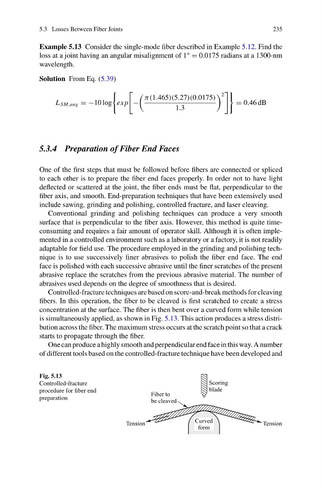
Controlled-fracture techniques are based on score-and-break methods for cleaving
fibers. In this operation, the fiber to be cleaved is first scratched to create a stress
concentration at the surface. The fiber is then bent over a curved form while tension
is simultaneously applied, as shown in Fig. 5.13. This action produces a stress distribution across the fiber. The maximum stress occurs at the scratch point so that a crack
starts to propagate through the fiber.
One can produce a highly smooth and perpendicular end face in this way. A number
of different tools based on the controlled-fracture technique have been developed and
Fig. 5.13
Controlled-fracture
procedure for fiber end
preparation
235
Example 5.13 Consider the single-mode fiber described in Example 5.12. Find the
loss at a joint having an angular misalignment of 1° = 0.0175 radians at a 1300-nm
wavelength.
Solution From Eq. (5.39)
L SM,ang = −10 log
ex p
−
π(1.465)(5.27)(0.0175)
1.3
2
= 0.46 dB
5.3.4 Preparation of Fiber End Faces
One of the first steps that must be followed before fibers are connected or spliced
to each other is to prepare the fiber end faces properly. In order not to have light
deflected or scattered at the joint, the fiber ends must be flat, perpendicular to the
fiber axis, and smooth. End-preparation techniques that have been extensively used
include sawing, grinding and polishing, controlled fracture, and laser cleaving.
Conventional grinding and polishing techniques can produce a very smooth
surface that is perpendicular to the fiber axis. However, this method is quite timeconsuming and requires a fair amount of operator skill. Although it is often implemented in a controlled environment such as a laboratory or a factory, it is not readily
adaptable for field use. The procedure employed in the grinding and polishing technique is to use successively finer abrasives to polish the fiber end face. The end
face is polished with each successive abrasive until the finer scratches of the present
abrasive replace the scratches from the previous abrasive material. The number of
abrasives used depends on the degree of smoothness that is desired.
Controlled-fracture techniques are based on score-and-break methods for cleaving
fibers. In this operation, the fiber to be cleaved is first scratched to create a stress
concentration at the surface. The fiber is then bent over a curved form while tension
is simultaneously applied, as shown in Fig. 5.13. This action produces a stress distribution across the fiber. The maximum stress occurs at the scratch point so that a crack
starts to propagate through the fiber.
One can produce a highly smooth and perpendicular end face in this way. A number
of different tools based on the controlled-fracture technique have been developed and
Fig. 5.13
Controlled-fracture
procedure for fiber end
preparation