

5.3 Losses Between Fiber Joints
227
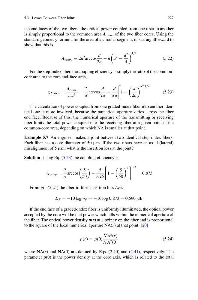
the end faces of the two fibers, the optical power coupled from one fiber to another
is simply proportional to the common area A comm of the two fiber cores. Using the
standard geometry formula for the area of a circular segment, it is straightforward to
show that this is
A comm = 2a
2 arccos
d
2a
− d
a
2
−
d
2
4
1/2
(5.22)
For the step-index fiber, the coupling efficiency is simply the ratio of the commoncore area to the core end-face area,
η F,step =
A comm
πa 2 =
2
π
arccos
d
2a
−
d
πa
1 −
d
2a
2
1/2
(5.23)
The calculation of power coupled from one graded-index fiber into another identical one is more involved, because the numerical aperture varies across the fiber
end face. Because of this, the numerical aperture of the transmitting or receiving
fiber limits the total power coupled into the receiving fiber at a given point in the
common-core area, depending on which NA is smaller at that point.
Example 5.7 An engineer makes a joint between two identical step-index fibers.
Each fiber has a core diameter of 50 μm. If the two fibers have an axial (lateral)
misalignment of 5 μm, what is the insertion loss at the joint?
Solution Using Eq. (5.23) the coupling efficiency is
η F,step =
2
π
arccos
5
50
−
5
π 25
1 −
5
50
2
1/2
= 0.873
From Eq. (5.21) the fiber-to-fiber insertion loss L F is
L F = −10 log η F = −10 log 0.873 = 0.590 dB
If the end face of a graded-index fiber is uniformly illuminated, the optical power
accepted by the core will be that power which falls within the numerical aperture of
the fiber. The optical power density p(r) at a point r on the fiber end is proportional
to the square of the local numerical aperture NA(r) at that point: [20]
p(r ) = p(0)
N A
2
(r )
N A 2 (0)
(5.24)
where NA(r) and NA(0) are defined by Eqs. (2.40) and (2.41), respectively. The
parameter p(0) is the power density at the core axis, which is related to the total
227
the end faces of the two fibers, the optical power coupled from one fiber to another
is simply proportional to the common area A comm of the two fiber cores. Using the
standard geometry formula for the area of a circular segment, it is straightforward to
show that this is
A comm = 2a
2 arccos
d
2a
− d
a
2
−
d
2
4
1/2
(5.22)
For the step-index fiber, the coupling efficiency is simply the ratio of the commoncore area to the core end-face area,
η F,step =
A comm
πa 2 =
2
π
arccos
d
2a
−
d
πa
1 −
d
2a
2
1/2
(5.23)
The calculation of power coupled from one graded-index fiber into another identical one is more involved, because the numerical aperture varies across the fiber
end face. Because of this, the numerical aperture of the transmitting or receiving
fiber limits the total power coupled into the receiving fiber at a given point in the
common-core area, depending on which NA is smaller at that point.
Example 5.7 An engineer makes a joint between two identical step-index fibers.
Each fiber has a core diameter of 50 μm. If the two fibers have an axial (lateral)
misalignment of 5 μm, what is the insertion loss at the joint?
Solution Using Eq. (5.23) the coupling efficiency is
η F,step =
2
π
arccos
5
50
−
5
π 25
1 −
5
50
2
1/2
= 0.873
From Eq. (5.21) the fiber-to-fiber insertion loss L F is
L F = −10 log η F = −10 log 0.873 = 0.590 dB
If the end face of a graded-index fiber is uniformly illuminated, the optical power
accepted by the core will be that power which falls within the numerical aperture of
the fiber. The optical power density p(r) at a point r on the fiber end is proportional
to the square of the local numerical aperture NA(r) at that point: [20]
p(r ) = p(0)
N A
2
(r )
N A 2 (0)
(5.24)
where NA(r) and NA(0) are defined by Eqs. (2.40) and (2.41), respectively. The
parameter p(0) is the power density at the core axis, which is related to the total