

220
5 Optical Power Coupling
where P 50 is the power expected in the fiber at the 50-m point based on the launch
NA. The degree of mode coupling occurring in a fiber is primarily a function of the
core-cladding index difference. It can thus vary significantly among different fiber
types. Because most optical fibers attain 80–90% of their equilibrium NA after about
50 m, it is the value of NA eq that is important when calculating launched optical
power in multimode fibers.
5.2 Coupling Improvement with Lensing Schemes
The optical power-launching analysis given in Sect. 5.1 is based on centering a
flat fiber end face directly over the light source as close to it as possible. If the
source-emitting area is larger than the fiber-core area, then the resulting optical
power coupled into the fiber is the maximum that can be achieved. This is a result
of fundamental energy and radiance conservation principles [6]. However, if the
emitting area of the source is smaller than the core area, a miniature lens may be
placed between the source and the fiber to improve the power-coupling efficiency.
The function of the microlens is to magnify the emitting area of the source to
match the core area of the fiber end face exactly. If the emitting area is increased by
a magnification factor M, the solid angle within which optical power is coupled to
the fiber from the source is increased by the same factor.
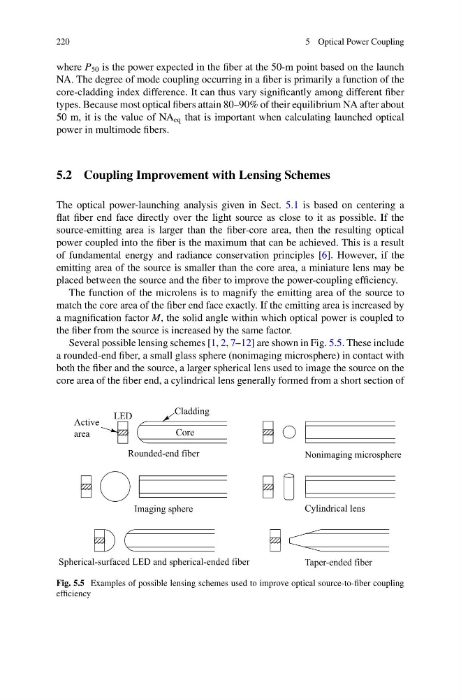
Several possible lensing schemes [1, 2, 7–12] are shown in Fig. 5.5. These include
a rounded-end fiber, a small glass sphere (nonimaging microsphere) in contact with
both the fiber and the source, a larger spherical lens used to image the source on the
core area of the fiber end, a cylindrical lens generally formed from a short section of
Fig. 5.5 Examples of possible lensing schemes used to improve optical source-to-fiber coupling
efficiency
5 Optical Power Coupling
where P 50 is the power expected in the fiber at the 50-m point based on the launch
NA. The degree of mode coupling occurring in a fiber is primarily a function of the
core-cladding index difference. It can thus vary significantly among different fiber
types. Because most optical fibers attain 80–90% of their equilibrium NA after about
50 m, it is the value of NA eq that is important when calculating launched optical
power in multimode fibers.
5.2 Coupling Improvement with Lensing Schemes
The optical power-launching analysis given in Sect. 5.1 is based on centering a
flat fiber end face directly over the light source as close to it as possible. If the
source-emitting area is larger than the fiber-core area, then the resulting optical
power coupled into the fiber is the maximum that can be achieved. This is a result
of fundamental energy and radiance conservation principles [6]. However, if the
emitting area of the source is smaller than the core area, a miniature lens may be
placed between the source and the fiber to improve the power-coupling efficiency.
The function of the microlens is to magnify the emitting area of the source to
match the core area of the fiber end face exactly. If the emitting area is increased by
a magnification factor M, the solid angle within which optical power is coupled to
the fiber from the source is increased by the same factor.
Several possible lensing schemes [1, 2, 7–12] are shown in Fig. 5.5. These include
a rounded-end fiber, a small glass sphere (nonimaging microsphere) in contact with
both the fiber and the source, a larger spherical lens used to image the source on the
core area of the fiber end, a cylindrical lens generally formed from a short section of
Fig. 5.5 Examples of possible lensing schemes used to improve optical source-to-fiber coupling
efficiency