

5.1 Source-to-Fiber Power Coupling
215
= π
2
(0.0035 cm)
2
150 W/
cm
2 sr
(0.20)
2
= 0.725 mW
For the case when the fiber end-face area is smaller than the emitting surface area,
one needs to use Eq. (5.8). Thus the coupled power is less than the above case by the
ratio of the radii squared:
P L E D,step =
25 μm
35 μm
2
P s (N A)
2
=
25 μm
35 μm
2
(0.725 mW)
= 0.37 mW = −4.32 dBm
In the case of a graded-index fiber, the numerical aperture depends on the distance
r from the fiber axis through the relationship defined by Eq. (2.40). Thus using Eqs.
(2.40) and (2.41), the power coupled from a surface-emitting LED into a graded-index
fiber becomes (for r s < a)
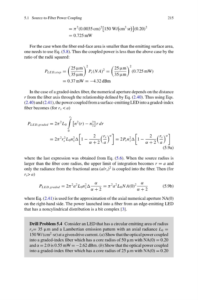
P L E D,graded = 2π
2 L 0
r s
0
n
2
(r ) − n
2
2
r dr
= 2π
2 r
2
s L 0 n
2
1
1 −
2
α + 2
r s
a
α
= 2P s n
2
1
1 −
2
α + 2
r s
a
α
(5.9a)
where the last expression was obtained from Eq. (5.6). When the source radius is
larger than the fiber core radius, the upper limit of integration becomes r = a and
only the radiance from the fractional area (a/r s )
2 is coupled into the fiber. Then (for
r s > a)
P L E D,graded = 2π
2 a
2 L 0 n
2
1
α
α + 2
= π
2 a
2 L 0 N A(0)
2 α
α + 2
(5.9b)
where Eq. (2.41) is used for the approximation of the axial numerical aperture NA(0)
on the right-hand side. The power launched into a fiber from an edge-emitting LED
that has a noncylindrical distribution is a bit complex [3].
Drill Problem 5.4 Consider an LED that has a circular emitting area of radius
r s = 35 μm and a Lambertian emission pattern with an axial radiance L 0 =
150 W/ (cm
2
·sr) at a given drive current. (a) Show that the optical power coupled
into a graded-index fiber which has a core radius of 50 μm with NA(0) = 0.20
and α = 2.0 is 0.55 mW = −2.62 dBm. (b) Show that the optical power coupled
into a graded-index fiber which has a core radius of 25 μm with NA(0) = 0.20
215
= π
2
(0.0035 cm)
2
150 W/
cm
2 sr
(0.20)
2
= 0.725 mW
For the case when the fiber end-face area is smaller than the emitting surface area,
one needs to use Eq. (5.8). Thus the coupled power is less than the above case by the
ratio of the radii squared:
P L E D,step =
25 μm
35 μm
2
P s (N A)
2
=
25 μm
35 μm
2
(0.725 mW)
= 0.37 mW = −4.32 dBm
In the case of a graded-index fiber, the numerical aperture depends on the distance
r from the fiber axis through the relationship defined by Eq. (2.40). Thus using Eqs.
(2.40) and (2.41), the power coupled from a surface-emitting LED into a graded-index
fiber becomes (for r s < a)
P L E D,graded = 2π
2 L 0
r s
0
n
2
(r ) − n
2
2
r dr
= 2π
2 r
2
s L 0 n
2
1
1 −
2
α + 2
r s
a
α
= 2P s n
2
1
1 −
2
α + 2
r s
a
α
(5.9a)
where the last expression was obtained from Eq. (5.6). When the source radius is
larger than the fiber core radius, the upper limit of integration becomes r = a and
only the radiance from the fractional area (a/r s )
2 is coupled into the fiber. Then (for
r s > a)
P L E D,graded = 2π
2 a
2 L 0 n
2
1
α
α + 2
= π
2 a
2 L 0 N A(0)
2 α
α + 2
(5.9b)
where Eq. (2.41) is used for the approximation of the axial numerical aperture NA(0)
on the right-hand side. The power launched into a fiber from an edge-emitting LED
that has a noncylindrical distribution is a bit complex [3].
Drill Problem 5.4 Consider an LED that has a circular emitting area of radius
r s = 35 μm and a Lambertian emission pattern with an axial radiance L 0 =
150 W/ (cm
2
·sr) at a given drive current. (a) Show that the optical power coupled
into a graded-index fiber which has a core radius of 50 μm with NA(0) = 0.20
and α = 2.0 is 0.55 mW = −2.62 dBm. (b) Show that the optical power coupled
into a graded-index fiber which has a core radius of 25 μm with NA(0) = 0.20