

210
5 Optical Power Coupling
that are either perpendicular to the axis or that are polished at a slight angle to prevent
back reflections of optical power into the device.
An alternate arrangement consists of light sources and optical fiber receptacles
that are integrated within a transceiver package. To achieve fiber-to-fiber coupling in
this case, the fiber connector from a cable is simply mated to the built-in connector in
the transceiver package. Among the various commercially available configurations
are the popular small-form- factor (SFF) and the SFF pluggable (SFP) devices.
5.1 Source-to-Fiber Power Coupling
A convenient and useful measure of the optical output of a luminescent source is its
radiance at a given diode drive current. Radiance is traditionally designated by the
symbol L and is the optical power radiated into a unit solid angle per unit emitting
surface area. It is generally specified in terms of watts per square centimeter per
steradian. Because the optical power that can be coupled into a fiber depends on the
radiance (i.e., on the spatial distribution of the optical power), the radiance of an
optical source rather than the total output power is the important parameter when
considering source-to-fiber coupling efficiencies.
5.1.1 Light Source Emission Patterns
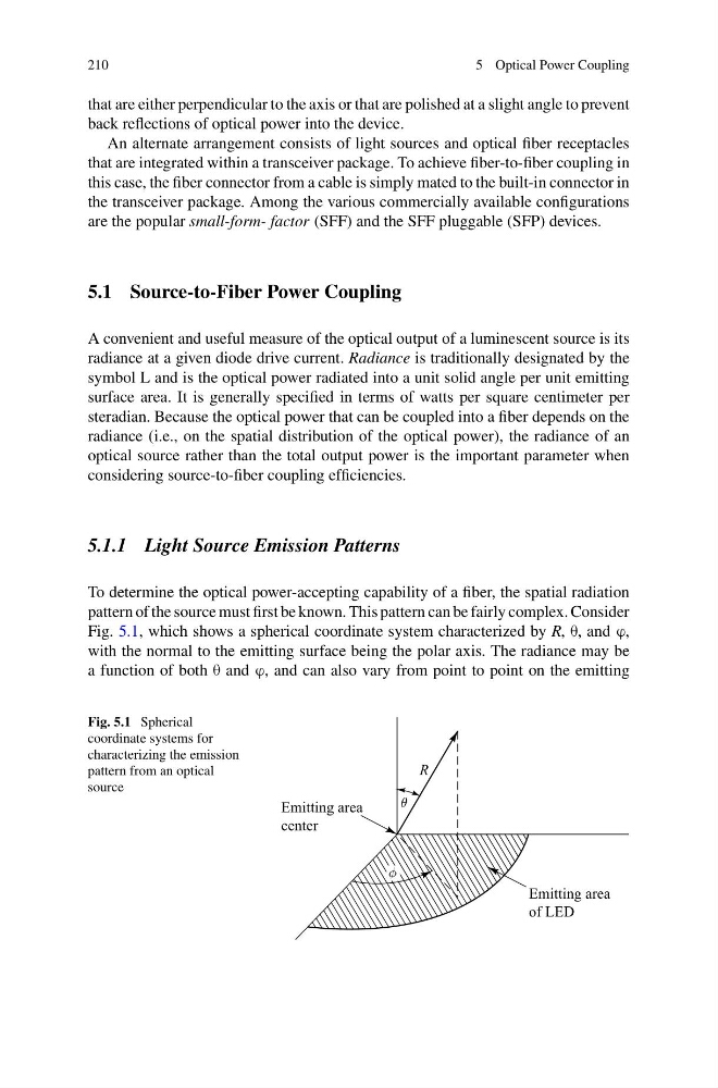
To determine the optical power-accepting capability of a fiber, the spatial radiation
pattern of the source must first be known. This pattern can be fairly complex. Consider
Fig. 5.1, which shows a spherical coordinate system characterized by R, θ, and ϕ,
with the normal to the emitting surface being the polar axis. The radiance may be
a function of both θ and ϕ, and can also vary from point to point on the emitting
Fig. 5.1 Spherical
coordinate systems for
characterizing the emission
pattern from an optical
source
5 Optical Power Coupling
that are either perpendicular to the axis or that are polished at a slight angle to prevent
back reflections of optical power into the device.
An alternate arrangement consists of light sources and optical fiber receptacles
that are integrated within a transceiver package. To achieve fiber-to-fiber coupling in
this case, the fiber connector from a cable is simply mated to the built-in connector in
the transceiver package. Among the various commercially available configurations
are the popular small-form- factor (SFF) and the SFF pluggable (SFP) devices.
5.1 Source-to-Fiber Power Coupling
A convenient and useful measure of the optical output of a luminescent source is its
radiance at a given diode drive current. Radiance is traditionally designated by the
symbol L and is the optical power radiated into a unit solid angle per unit emitting
surface area. It is generally specified in terms of watts per square centimeter per
steradian. Because the optical power that can be coupled into a fiber depends on the
radiance (i.e., on the spatial distribution of the optical power), the radiance of an
optical source rather than the total output power is the important parameter when
considering source-to-fiber coupling efficiencies.
5.1.1 Light Source Emission Patterns
To determine the optical power-accepting capability of a fiber, the spatial radiation
pattern of the source must first be known. This pattern can be fairly complex. Consider
Fig. 5.1, which shows a spherical coordinate system characterized by R, θ, and ϕ,
with the normal to the emitting surface being the polar axis. The radiance may be
a function of both θ and ϕ, and can also vary from point to point on the emitting
Fig. 5.1 Spherical
coordinate systems for
characterizing the emission
pattern from an optical
source