

168
4 Light Sources for Fiber Links
τ =
τ r τ nr
τ r + τ nr
=
30 × 300
30 + 300
ns = 23.1 ns
(b) Using Eq. (4.10), the internal quantum efficiency is
η int =
τ
τ r
=
23.1
30
= 0.77
(c) Substituting this into Eq. (4.13) yields an internal power level of
P int = η int
hcI
qλ
= 0.77
(6.6256 × 10
−34 J s)(3 × 10
8 m/s)(0.040 A)
(1.602 × 10 −19 C)(1.31 × 10 −6 m)
= 29.2 mW
Not all internally generated photons will exit the device. To find the emitted power,
one needs to consider the external quantum efficiency η ext . This is defined as the ratio
of the photons emitted from the LED to the number of internally generated photons.
To find the external quantum efficiency, one needs to take into account reflection
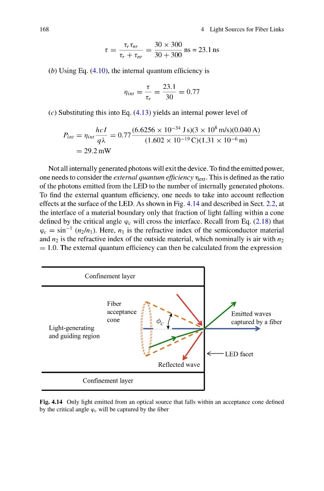
effects at the surface of the LED. As shown in Fig. 4.14 and described in Sect. 2.2, at
the interface of a material boundary only that fraction of light falling within a cone
defined by the critical angle ϕ c will cross the interface. Recall from Eq. (2.18) that
ϕ c = sin
−1 (n 2 /n 1 ). Here, n 1 is the refractive index of the semiconductor material
and n 2 is the refractive index of the outside material, which nominally is air with n 2
= 1.0. The external quantum efficiency can then be calculated from the expression
LED facet
Emitted waves
captured by a fiber
Reflected wave
Confinement layer
Confinement layer
Light-generating
and guiding region
Fiber
acceptance
cone
Fig. 4.14 Only light emitted from an optical source that falls within an acceptance cone defined
by the critical angle ϕ c will be captured by the fiber
4 Light Sources for Fiber Links
τ =
τ r τ nr
τ r + τ nr
=
30 × 300
30 + 300
ns = 23.1 ns
(b) Using Eq. (4.10), the internal quantum efficiency is
η int =
τ
τ r
=
23.1
30
= 0.77
(c) Substituting this into Eq. (4.13) yields an internal power level of
P int = η int
hcI
qλ
= 0.77
(6.6256 × 10
−34 J s)(3 × 10
8 m/s)(0.040 A)
(1.602 × 10 −19 C)(1.31 × 10 −6 m)
= 29.2 mW
Not all internally generated photons will exit the device. To find the emitted power,
one needs to consider the external quantum efficiency η ext . This is defined as the ratio
of the photons emitted from the LED to the number of internally generated photons.
To find the external quantum efficiency, one needs to take into account reflection
effects at the surface of the LED. As shown in Fig. 4.14 and described in Sect. 2.2, at
the interface of a material boundary only that fraction of light falling within a cone
defined by the critical angle ϕ c will cross the interface. Recall from Eq. (2.18) that
ϕ c = sin
−1 (n 2 /n 1 ). Here, n 1 is the refractive index of the semiconductor material
and n 2 is the refractive index of the outside material, which nominally is air with n 2
= 1.0. The external quantum efficiency can then be calculated from the expression
LED facet
Emitted waves
captured by a fiber
Reflected wave
Confinement layer
Confinement layer
Light-generating
and guiding region
Fiber
acceptance
cone
Fig. 4.14 Only light emitted from an optical source that falls within an acceptance cone defined
by the critical angle ϕ c will be captured by the fiber